Composite board integrated wall module and installation method thereof

An installation method and integrated wall technology, applied in the field of architectural decoration, can solve problems such as poor sound insulation effect, complicated processing and installation, and damage to ALC boards, and achieve good sound insulation effect, high installation flatness, and improved installation efficiency.

Pending Publication Date: 2021-12-21
TIANJIN DAYIN BUILDING MATERIAL CO LTD
View PDF9 Cites 0 Cited by
  • Summary
  • Abstract
  • Description
  • Claims
  • Application Information

AI Technical Summary

Problems solved by technology

[0002] At present, the traditional heaven and earth keels are all U-shaped. It is extremely difficult for the ALC board to advance into the two opposite U-shaped grooves, which can easily cause damage to the ALC board. There is a lot of dust and there is a problem of noise pollution, and it cannot be cross-worked with other processes, such as: scraping putty and painting the top surface, and the dust from the slotting of the ALC board will pollute it; when the ALC board is fixed to the structural wall, pins are required 1. Steel bars are inserted obliquely into the structural wall, and careless operation will cause damage to the structural wall. In addition, the ALC board has the problem of being fragile, poor impact resistance, and difficult to carry due to its heavy weight. At present, the traditional ALC wall and structural roof The surfaces, floors, structural walls, and the gaps between two adjacent walls are all filled with cement glue. There are technical problems such as long material curing period and poor sound insulation effect. Moreover, the traditional wall methods are different, and various materials On-site processing (keel, rock wool, gypsum board) is required, and there are problems such as poor construction environment, noise pollution, waste of materials, and low work efficiency
[0003] At present, the construction quality of the traditional wall method completely depends on the technical level of the construction personnel. The skill level of the operators is uneven, and the construction quality cannot be unified. There are the following disadvantages:
[0004] 1. The traditional ALC wall has many components, and the on-site cutting and installation procedures are complicated and labor-intensive
[0005] 2. The traditional heaven and earth keels are all U-shaped, and it is extremely difficult for the ALC board to advance into the two opposite U-shaped grooves, which can easily cause damage to the ALC board
[0006] 3. In particular, water and electricity pipelines need to be slotted and embedded on site, causing a lot of dust and noise pollution, and cannot be cross-operated with other processes. For example, the top surface is putty and painted, and the dust from the slotting of the ALC board will pollute it
[0007] 4. When the ALC board is fixed to the structural wall, it needs to be pinned and the steel bar is inserted obliquely into the structural wall. Careless operation will cause damage to the structural wall, and the ALC board itself is fragile, has poor impact resistance, and is difficult to install due to its heavy weight. carry
[0008] 5. The traditional ALC wall and the top surface of the structure, the ground, the structure wall, and the gaps between two adjacent walls are filled with cement glue, which has a long curing period and poor sound insulation effect
Complicated processing and installation
[0010] 7. After the ALC wall is installed, the flatness of the board surface is poor, and it still needs putty to smooth it, or lay plasterboard to level it, and increase the process to cause waste of materials and time

Method used


Image

  • Composite board integrated wall module and installation method thereof
  • Composite board integrated wall module and installation method thereof
  • Composite board integrated wall module and installation method thereof

Examples


Embodiment 1

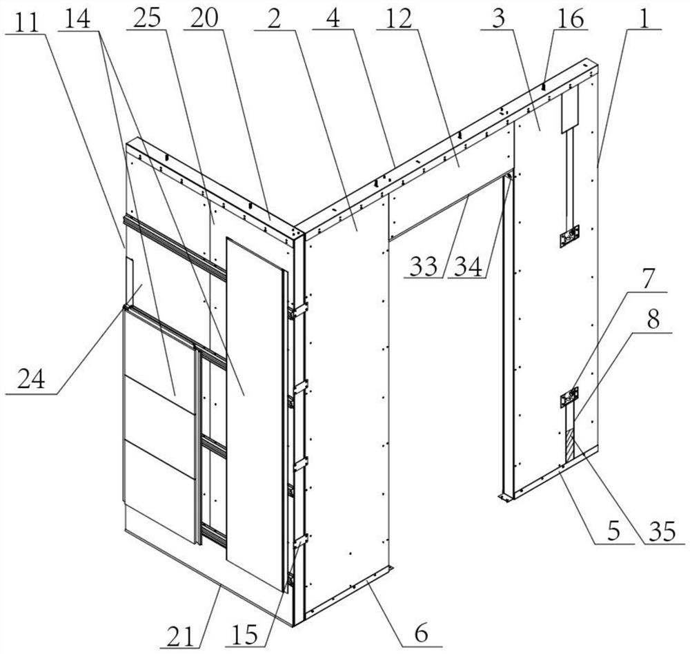
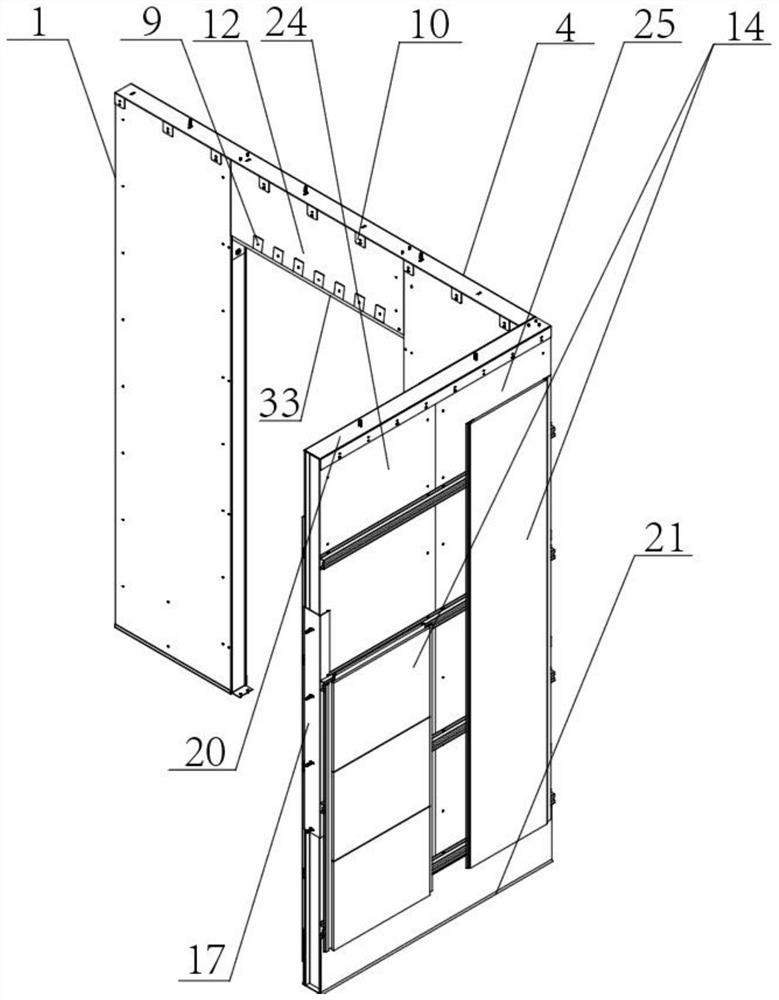
[0061] figure 1 and figure 2 All are three-dimensional structural schematic diagrams of a composite board integrated wall module disclosed in the present invention, image 3 and Figure 4 All are structural representations of decorative panels in the present invention, Figure 5 It is a schematic diagram of the enlarged structure of the top keel A in the present invention, Figure 6 It is a schematic diagram of the enlarged structure of vertical slats in the present invention, Figure 7 for Figure 6 Schematic diagram of the partially enlarged structure at A, Figure 8 It is a schematic diagram of the cross-sectional structure of the connecting gap between the vertical strip board C and the vertical strip board D in the present invention, as Figure 1 to Figure 8 Shown is a composite board integrated wall module and its installation method. The modular wall includes: a sky keel, a ground keel, a wall A1 and a wall B11, and the sky keel and the ground keel are respective...

Embodiment 2

[0063] figure 1 and figure 2 All are three-dimensional structural schematic diagrams of a composite board integrated wall module disclosed in the present invention, image 3 and Figure 4 All are structural representations of decorative panels in the present invention, Figure 5 It is a schematic diagram of the enlarged structure of the top keel A in the present invention, Figure 6 It is a schematic diagram of the enlarged structure of vertical slats in the present invention, Figure 7 for Figure 6 Schematic diagram of the partially enlarged structure at A, Figure 8 It is a schematic diagram of the cross-sectional structure of the connecting gap between the vertical strip board C and the vertical strip board D in the present invention, as Figure 1 to Figure 8 Shown is a composite board integrated wall module and its installation method. The vertical strip board B3 in the modular wall is provided with a wire groove 26, and an electric unit is installed inside the wir...

Embodiment 3

[0065] figure 1 and figure 2 All are three-dimensional structural schematic diagrams of a composite board integrated wall module disclosed in the present invention, image 3 and Figure 4 All are structural representations of decorative panels in the present invention, Figure 5 It is a schematic diagram of the enlarged structure of the top keel A in the present invention, Figure 6 It is a schematic diagram of the enlarged structure of vertical slats in the present invention, Figure 7 for Figure 6 Schematic diagram of the partially enlarged structure at A, Figure 8 It is a schematic diagram of the cross-sectional structure of the connecting gap between the vertical strip board C and the vertical strip board D in the present invention, as Figure 1 to Figure 8 In the shown composite board integrated wall module and its installation method, a card slot 18 is formed in the sky keel and the ground keel along the length direction of the wall A1, and the wall A1 is insert...


PUM


Abstract

The invention relates to the technical field of building decoration, and particularly relates to a composite board integrated wall module and an installation method thereof. The composite board integrated wall module comprises a ceiling keel, a floor keel, a wall A and a wall B; the ceiling keel and the floor keel are connected to the upper end and the lower end of the wall A and the upper end and the lower end of the wall B respectively; the wall A comprises a transverse strip plate, a vertical strip plate A and a vertical strip plate B; the vertical strip plate A and the vertical strip plate B are fixedly connected to the two sides of the transverse strip plate A respectively; the wall B is arranged on one side of the vertical strip plate A; the wall B and the vertical strip plate A are fixedly connected; the wall B comprises a vertical strip plate C and a vertical strip plate D; the vertical strip plate C and the vertical strip plate D are connected; a sound insulation pad is arranged at the joint between the vertical strip plate C and the vertical strip plate D; and the sound insulation pad is bonded to the gap between the vertical strip plate C and the vertical strip plate D through bonding glue. The L-shaped ceiling keel and the L-shaped floor keel are adopted, the wall module can be easily and smoothly pushed into clamping grooves of the keels, the installation efficiency is improved by two times, and wall collision is avoided.

Description

technical field [0001] The invention relates to the technical field of architectural decoration, in particular to a composite panel integrated wall module and an installation method thereof. Background technique [0002] At present, the traditional heaven and earth keels are all U-shaped. It is extremely difficult for the ALC board to advance into the two opposite U-shaped grooves, which can easily cause damage to the ALC board. There is a lot of dust and there is a problem of noise pollution, and it cannot be cross-worked with other processes, such as: scraping putty and painting the top surface, and the dust from the slotting of the ALC board will pollute it; when the ALC board is fixed to the structural wall, pins are required 1. Steel bars are inserted obliquely into the structural wall, and careless operation will cause damage to the structural wall. In addition, the ALC board has the problem of being fragile, poor impact resistance, and difficult to carry due to its he...

Claims


Application Information

Patent Timeline
Patent Type & Authority Applications(China)
IPC IPC(8): E04F13/072E04F13/075E04F13/074E04F13/076E04F13/22E04G21/14
CPCE04F13/08E04F13/0889E04F13/0891E04F13/0803E04G21/14E04F2290/02E04F2290/041
Inventor 闫俊杰梅能敏王龙涛赵静邵俊义贾路
Owner TIANJIN DAYIN BUILDING MATERIAL CO LTD
Why Eureka
Try Eureka