Sensitive detection unit of nuclear magnetic resonance gyroscope and manufacturing method of the unit
What is AI technical title?
AI technical title is built by Patsnap AI team. It summarizes the technical point description of the patent document.
A nuclear magnetic resonance gyroscope and sensitive detection technology, which is applied in the direction of instruments, measuring devices, steering sensing equipment, etc., can solve the problems of low precision of sensitive detection units and cannot meet the requirements of nuclear magnetic resonance gyroscopes, and achieve high practical value, reliable performance, The effect of improving the overall accuracy
Inactive Publication Date: 2017-03-08
HARBIN ENG UNIV +1
View PDF5 Cites 0 Cited by
Summary
Abstract
Description
Claims
Application Information
AI Technical Summary
This helps you quickly interpret patents by identifying the three key elements:
Problems solved by technology
Method used
Benefits of technology
Problems solved by technology
[0003] The present invention is to solve the problem that the existing sensitive detection unit has low precision and cannot meet the requirements of the nuclear magnetic resonance gyroscope, and now provides a sensitive detection unit of the nuclear magnetic resonance gyroscope and a manufacturing method of the unit
Method used
Image
Click on the blue label to locate the original text in one second.
Reading with bidirectional positioning of images and text.
Examples
specific Embodiment approach 1
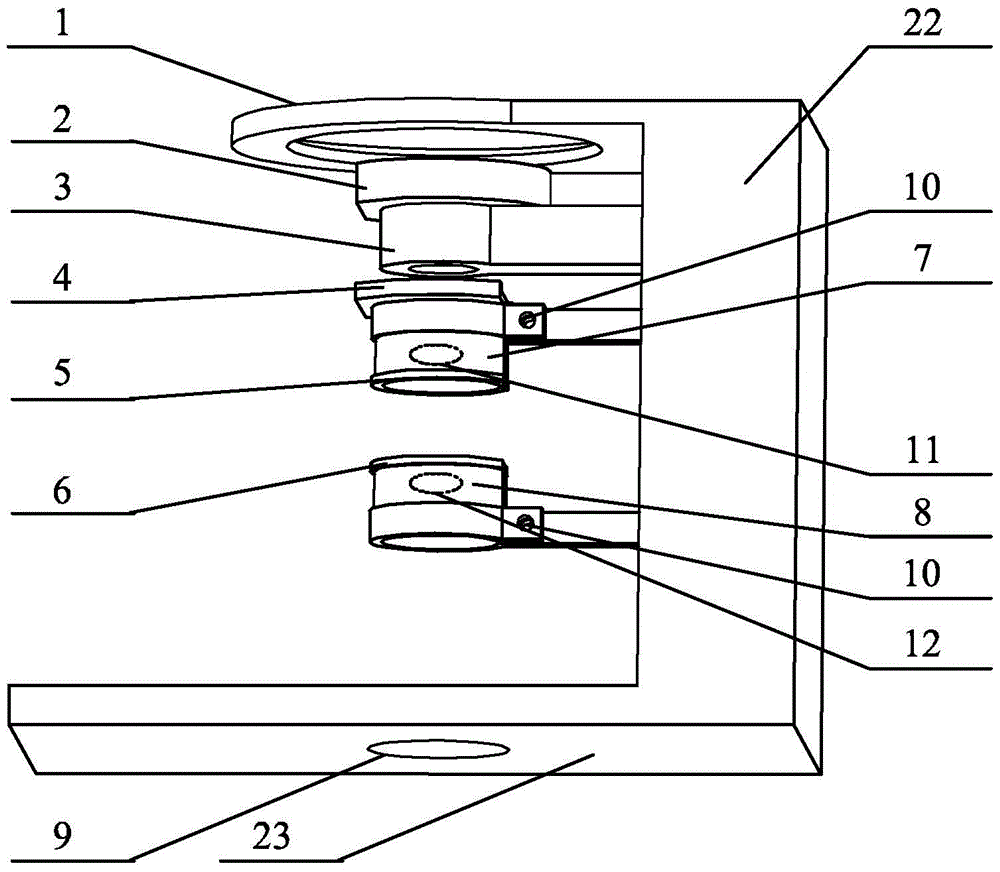
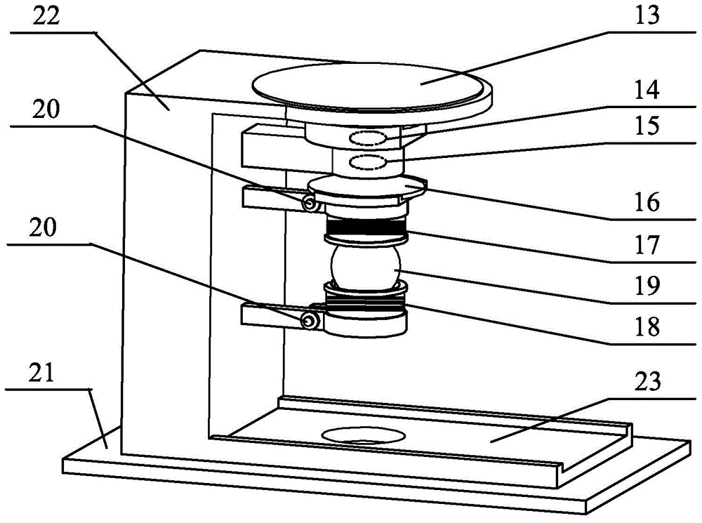
[0014] Specific implementation mode one: refer to figure 1 and figure 2 Specifically illustrate the present embodiment, the nuclear magnetic resonance gyroscope sensitive detection unit described in the present embodiment, it comprises: VCSEL laser device 13, polarizer 14, collimator lens 15, 1 / 4 wave plate 16, nuclear magnetic resonance gas chamber 19, Photodetector 21 and support;
[0015] The bracket includes: column 22, base 23, laser slot 1, polarizer slot 2, collimator lens slot 3, 1 / 4 wave plate slot 4, clamp 5 above the gas chamber, and clamp 6 below the gas chamber;
[0016] The column 22 is vertically fixed on the base 23, and the base 23 is provided with a photodetector light hole 9, a laser slot 1, a polarizer slot 2, a collimator lens slot 3, a 1 / 4 wave plate slot 4, Fixture 5 above the gas chamber and fixture 6 below the gas chamber are sequentially fixed on the column 22 from top to bottom, and laser slot 1, polarizer slot 2, collimator lens slot 3, 1 / 4 wave ...
specific Embodiment approach 2
[0022] Embodiment 2: This embodiment is a further description of the NMR gyroscope sensitive detection unit described in Embodiment 1. In this embodiment, the bracket is an integrated structure.
specific Embodiment approach 3
[0023] Embodiment 3: This embodiment is a further description of the NMR gyroscope sensitive detection unit described in Embodiment 1. In this embodiment, the material of the bracket is photosensitive resin.
PUM
Abstract
The invention relates to a nuclear magnetic resonance gyroscope sensitivity detection unit and a manufacturing method of the nuclear magnetic resonance gyroscope sensitivity detection unit and belongs to the field of atom sensors. The nuclear magnetic resonance gyroscope sensitivity detection unit aims to solve the problems that an existing sensitivity detection unit is low in accuracy and can not meet the requirements of a nuclear magnetic resonance gyroscope. According to the nuclear magnetic resonance gyroscope sensitivity detection unit and the manufacturing method of the nuclear magnetic resonance gyroscope sensitivity detection unit, the main structure is completed by means of the 3D printing technology, and the positions of all elements are directly limited; lasers emitted by a VCSEL laser device are polarized through a polarizer, collimated through a small-focal-length collimation lens and then emitted into a nuclear magnetic resonance air chamber after the polarization state is adjusted through a 1 / 4 wave plate; alkali metal atoms and inert gas atoms in an atom air chamber are pumped into an excited state through pump light first, and then the emitted light of the nuclear magnetic resonance air chamber is emitted to the photosensitive surface of a photoelectric detector to complete detection of nuclear magnetic resonance signals. The nuclear magnetic resonance gyroscope sensitivity detection unit and the manufacturing method of the nuclear magnetic resonance gyroscope sensitivity detection unit are suitable for development of a micro-structure nuclear magnetic resonance gyroscope system.
Description
technical field [0001] The invention belongs to the field of atomic sensors. Background technique [0002] The nuclear magnetic resonance atomic gyroscope is a sensor that uses the atomic nuclear magnetic resonance frequency change to detect the angle change. The sensitive detection unit is the core component of the entire gyroscope. Its stability and accuracy determine the overall nuclear magnetic resonance atomic gyroscope of the system. Detection accuracy, however, the existing sensitive detection unit has low precision, high power consumption, and large volume, which cannot meet the requirements of nuclear magnetic resonance gyroscopes. Therefore, how to design a sensitive detection unit with high precision, low power consumption, and small size has become a manufacturing The key to an MRI gyroscope. Contents of the invention [0003] The present invention aims to solve the problem that the existing sensitive detection unit has low precision and cannot meet the requir...
Claims
Application Information
Patent Timeline
Application Date:The date an application was filed.
Publication Date:The date a patent or application was officially published.
First Publication Date:The earliest publication date of a patent with the same application number.
Issue Date:Publication date of the patent grant document.
PCT Entry Date:The Entry date of PCT National Phase.
Estimated Expiry Date:The statutory expiry date of a patent right according to the Patent Law, and it is the longest term of protection that the patent right can achieve without the termination of the patent right due to other reasons(Term extension factor has been taken into account ).
Invalid Date:Actual expiry date is based on effective date or publication date of legal transaction data of invalid patent.

