Kerb laying vehicle

A technology of curbs and car bodies, which is applied in the field of road construction, can solve the problems of curb bruises, time-consuming and labor-intensive problems, and achieve the effects of facilitating construction, reducing labor intensity, and reducing intermediate transportation.

Inactive Publication Date: 2018-08-24
湖州华科建设工程质量检测有限公司
View PDF0 Cites 7 Cited by
  • Summary
  • Abstract
  • Description
  • Claims
  • Application Information

AI Technical Summary

Problems solved by technology

[0002] At present, in the field of road construction, the laying of curbs is basically carried by small carts and placed next to the laying tank, and then manually moved into the laying tank, which is not only time-consuming and laborious, but also easily causes curb damage.

Method used


Image

  • Kerb laying vehicle
  • Kerb laying vehicle
  • Kerb laying vehicle

Examples


Embodiment Construction

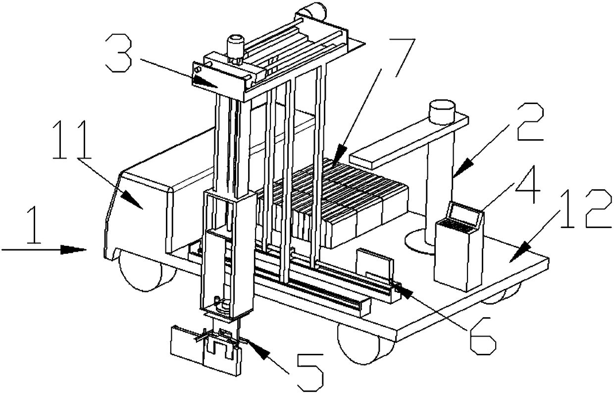
[0039] like Figure 1 to Figure 6 As shown, a curb laying vehicle includes a car assembly 1, a cantilever crane 2, a laying device 3, a control device 4, an alignment frame 5, an origin resting plate 6, and a curb 7;

[0040] The automobile assembly 1 includes a cab 11 and a car bucket 12;

[0041] The cantilever crane 2 is arranged on the vehicle body 12;

[0042] The car bucket 12 is also provided with an origin resting plate 6, a control device 4, and a laying device 3;

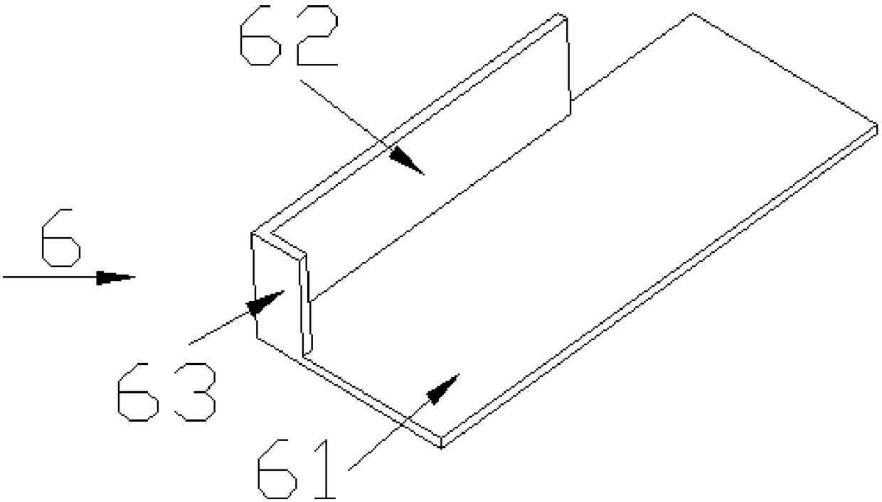
[0043] The origin resting plate 6 includes a resting bottom plate 61, on which a horizontal backrest board 62 and a longitudinal backrest board 63 are vertically arranged;

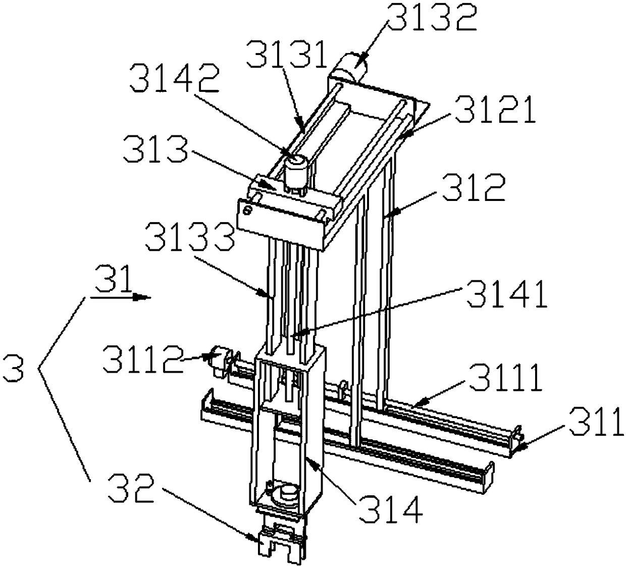
[0044] The laying device 3 includes a linkage mechanism 31 and a clamping device 32;

[0045] The clamping device 32 includes a first clamping plate 321, a second clamping plate 322, and a direction adjusting device 325;

[0046] The first clamping plate 321 is arranged vertically, the second clamping plate 322 is in a “Z” shape, a...


PUM


Abstract

The invention relates to the field of decoration construction, in particular to a kerb laying vehicle. The kerb laying vehicle comprises a vehicle assembly, a cantilever crane, a laying device, a control device, an alignment bracket, an original point placement board and kerbs. The kerb carrying step can be omitted to save time; besides, manual work is greatly reduced to save time and labor.

Description

Technical field: [0001] The invention relates to the field of road construction, in particular to a road curb laying vehicle. Background technique: [0002] At present, in the field of road construction, the laying of curbs is basically carried by a trolley and placed next to the laying trough, and then manually moved into the laying trough, which is not only time-consuming and laborious, but also easily causes bruises on the curb stones. Invention content: [0003] The purpose of the present invention is to provide a curb laying vehicle for the deficiencies of the prior art, which can not only reduce the steps of curb stone handling, save time, but also greatly reduce manual labor, saving time and effort. [0004] Technical solutions of the present invention are as follows: [0005] A road curb laying vehicle, including a car assembly, a cantilever crane, a laying device, a control device, an alignment frame, an origin resting plate, and a curb; [0006] The automobile ...

Claims


Application Information

Patent Timeline
Patent Type & Authority Applications(China)
IPC IPC(8): E01C19/52
CPCE01C19/52
Inventor 郑亮
Owner 湖州华科建设工程质量检测有限公司
Why Eureka
Try Eureka