
A follow-up self-locking hydraulic reset mechanism for a follow-up self-locking booster hydraulic cylinder

A hydraulic cylinder and reset mechanism technology, applied in the field of hydraulic cylinders, can solve the problems of operator safety accidents, inability to lock in time, large size of hydraulic locks, etc., and achieve the effect of sensitive and rapid response

Active Publication Date: 2020-10-16
江苏万川液压机械设备有限公司
View PDF3 Cites 0 Cited by
  • Summary
  • Abstract
  • Description
  • Claims
  • Application Information

AI Technical Summary

Problems solved by technology

[0004] 1. The oil circuit is self-locking, but due to the large size of the hydraulic lock, it is difficult to install and maintain in places where the installation space is limited; moreover, because the hydraulic lock spool cannot achieve "zero" leakage, when the oil cylinder is subjected to a large load Or as time goes by, the piston rod will still move and affect the locking effect, resulting in operator safety accidents and equipment damage
[0005] 2. Mechanical nut self-locking, because when the piston rod of the oil cylinder reaches the required position, manpower is required to rotate the nut on the piston rod of the oil cylinder to the end and contact the cylinder body of the oil cylinder to achieve the locking effect. There is a time sequence , you must wait for the piston rod of the oil cylinder to extend to the required position and then stop, and then artificially rotate the nut on the piston rod of the oil cylinder to the bottom to contact the cylinder body. Specific working conditions will prevent the construction from proceeding smoothly or cause safety accidents for operators and equipment damage
This will increase labor costs and increase labor intensity, and in some harsh environments such as: underground, underground and some dangerous places, the construction cannot even be carried out smoothly

Method used


Image

  • A follow-up self-locking hydraulic reset mechanism for a follow-up self-locking booster hydraulic cylinder
  • A follow-up self-locking hydraulic reset mechanism for a follow-up self-locking booster hydraulic cylinder
  • A follow-up self-locking hydraulic reset mechanism for a follow-up self-locking booster hydraulic cylinder

Examples


Embodiment Construction

[0029] In order to deepen the understanding of the present invention, the following will be described in detail in conjunction with the accompanying drawings and specific embodiments. The embodiments described in this specification are only used to explain the present invention, and are not intended to limit the present invention.

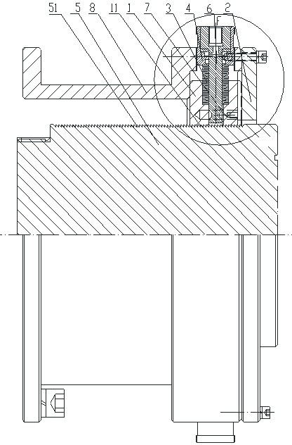
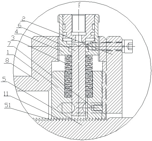
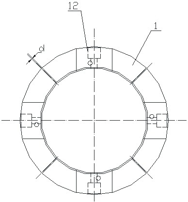
[0030] figure 1 and Figure 1a As shown, a follow-up self-locking hydraulic reset mechanism of a follow-up self-locking booster hydraulic cylinder of the present invention, the follow-up self-locking hydraulic reset mechanism includes a follow-up self-locking mechanism and a hydraulic reset mechanism, and the follow-up The self-locking mechanism includes a backstop rod 5, a backstop ring 1 and a disc spring 3. The backstop bar 5 has an outer ratchet 51 on the surface, and the outer ratchet 51 meshes with the inner ratchet 11 of the backstop ring 1. The backstop ring 1 Disc spring 3 is arranged inside.

[0031] The outer ratchet 51 of the stop rod...


PUM


Abstract

The invention discloses a servo self-locking hydraulic reset mechanism of a servo self-locking reinforcement hydraulic oil cylinder. The servo self-locking hydraulic reset mechanism comprises a servoself-locking mechanism and a hydraulic reset mechanism; the servo self-locking mechanism comprises a retaining rod, a retaining ring and a disk spring; the surface of the retaining rod is provided with outer ratchets, and the outer ratchets on the surface of the retaining rod is meshed with inner ratchets of the retaining ring; the disk spring is arranged in the retaining ring; and the hydraulic reset mechanism is a reset small hydraulic oil cylinder and enables the servo self-locking mechanism to be separated so that the locking state can be removed through the reset small hydraulic oil cylinder. The servo self-locking hydraulic reset mechanism of the servo self-locking reinforcement hydraulic oil cylinder is provided with the servo self-locking mechanism and the hydraulic reset mechanism, the mechanical self-locking mechanism is large in locking force and safe and reliable in locking, the reset small hydraulic oil cylinder overcomes pulling of the compression force of the disk spring, the retaining ring moves towards the outer side so as to be separated from the part, engaged with the retaining rod, of the retaining ring, accordingly, the portion, connected with the other end ofthe retaining rod is drawn back freely, response is flexible and quick, and safety and reliability are achieved without manual control.

Description

technical field [0001] The invention relates to a hydraulic oil cylinder, in particular to a follow-up self-locking hydraulic reset mechanism of a follow-up self-locking power-increasing hydraulic oil cylinder. Background technique [0002] At present, hydraulic cylinder self-locking is divided into oil circuit self-locking and mechanical self-locking. Oil circuit self-locking is to install a hydraulic valve to maintain pressure, so that the hydraulic oil of the oil cylinder does not return to the oil tank, and the oil chamber of the oil cylinder is filled with a certain pressure. Oil. The mechanical nut type self-locking is to install a nut on the piston rod of the oil cylinder. When the piston rod of the oil cylinder reaches the required position, turn the nut on the piston rod of the oil cylinder to the end to contact the cylinder body, so that the piston rod will fixed to the desired position. When the oil cylinder needs to be retracted, the nut is screwed up to allow ...

Claims


Application Information

Patent Timeline
Patent Type & Authority Patents(China)
IPC IPC(8): F15B15/26
CPCF15B15/26
Inventor 钱明慧钱小刚嵇鹏
Owner 江苏万川液压机械设备有限公司
Learn More