
Refrigerator provided with air channel assembly and control method thereof

A technology for air duct assembly and fan assembly, which is applied to household refrigeration devices, lighting and heating equipment, cooling fluid circulation devices, etc., can solve the problems of temperature rise in the freezer and food deterioration in the freezer, and achieves a simple structure and avoids temperature return. Large, easy-to-use effects

Pending Publication Date: 2018-08-24
CHANGHONG MEILING CO LTD
View PDF5 Cites 9 Cited by
  • Summary
  • Abstract
  • Description
  • Claims
  • Application Information

AI Technical Summary

Problems solved by technology

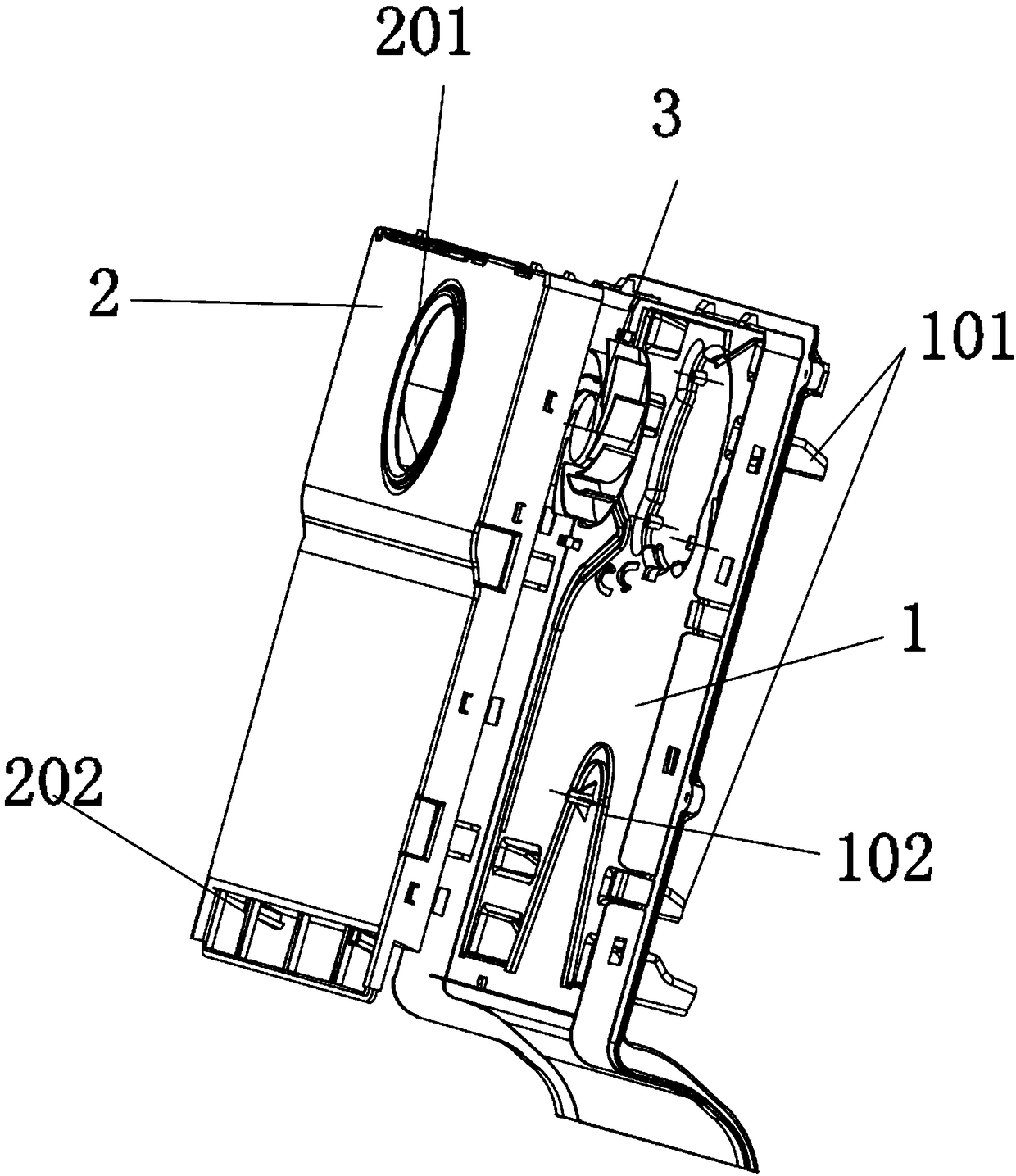
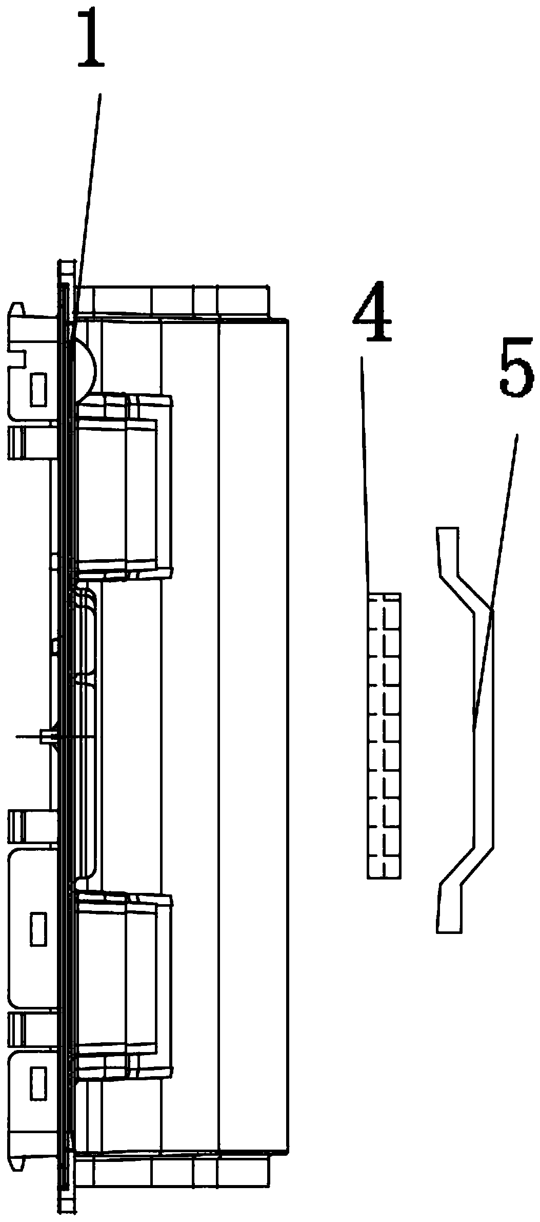
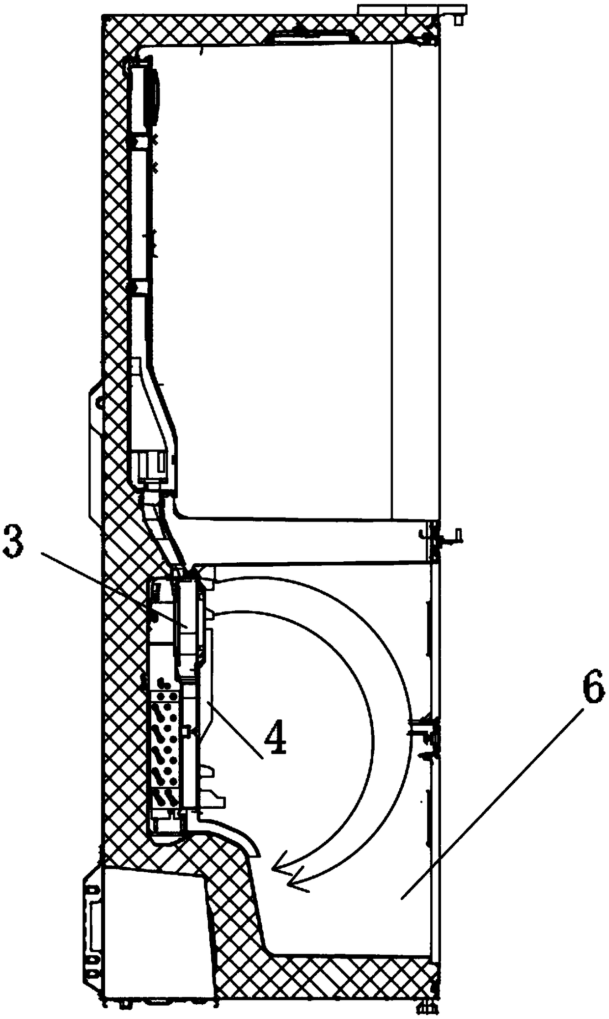
[0004] The object of the present invention is to provide an air duct assembly of a refrigerator and the refrigerator thereof. A cavity is designed in the front cover of the air duct, and the interior is filled with a cool storage agent. A controller is arranged in the box, and the fan assembly and frequency conversion compression are controlled by the controller. The rotation speed of the machine makes the cold storage agent store cold, which solves the problem that the temperature of the freezing chamber rises when the defrosting heater heats up the existing air-cooled refrigerator, which leads to the deterioration of the food in the freezing chamber

Method used


Image

  • Refrigerator provided with air channel assembly and control method thereof
  • Refrigerator provided with air channel assembly and control method thereof
  • Refrigerator provided with air channel assembly and control method thereof

Examples


Embodiment Construction

[0035] The following will clearly and completely describe the technical solutions in the embodiments of the present invention with reference to the accompanying drawings in the embodiments of the present invention. Obviously, the described embodiments are only some, not all, embodiments of the present invention. Based on the embodiments of the present invention, all other embodiments obtained by persons of ordinary skill in the art without creative efforts fall within the protection scope of the present invention.

[0036] In the description of the present invention, it should be understood that the terms "inside", "a surface", "upper" and the like indicate orientation or positional relationship, and are only for the convenience of describing the present invention and simplifying the description, rather than indicating or implying Any assembly or element must have a specific orientation, be constructed and operate in a specific orientation, and thus should not be construed as l...


PUM


Abstract

The invention discloses a refrigerator provided with an air channel assembly and a control method thereof, and relates to the technical field of refrigerators. The refrigerator provided with the air channel assembly comprises a refrigerator body in which the air channel assembly is arranged, wherein the air channel assembly comprises a fan assembly, a front cover plate of an air channel, and a rear cover of the air channel; the rear cover of the air channel covers the front cover plate of the air channel; an air channel chamber is formed between the front cover plate of the air channel and therear cover of the air channel; a plurality of freezing air outlets are formed in one surface of the front cover plate of the air channel; at least one interlayer chamber body which is filled with a phase-changed coolant is arranged on the front cover plate of the air channel; a controller is arranged in the refrigerator body and is correspondingly connected to a variable-frequency compressor, thefan assembly and a room temperature sensor. According to the refrigerator provided with the air channel assembly and the control method thereof, an empty chamber which is filled with the coolant is designed in the front cover plate of the air channel; the controller is arranged in the refrigerator body and is used for controlling the rotating speed of the fan assembly and the variable-frequency compressor; and the coolant is used for storing cold, and thus the problem that the temperature of a freezing chamber of an air-cooled refrigerator increases again while a defrosting heater performs heating, resulting in the spoilage of foods in the freezing chamber, can be avoided.

Description

technical field [0001] The invention belongs to the technical field of refrigerators, in particular to a refrigerator with an air duct assembly and a control method thereof. Background technique [0002] Air-cooled refrigerators use fans to force convection to exchange heat between the hot air in the compartment and the evaporator, thereby achieving the purpose of cooling the box. After a long period of cooling, the air-cooled refrigerator needs to be defrosted. Generally, it is judged according to the running time and sensor temperature. The defrosting heater is used to heat the evaporator, and the defrosting is stopped after reaching a certain temperature. [0003] However, when the existing air-cooled refrigerator is heated by the defrosting heater, the temperature of the freezer is also easy to rise, and in some cases the temperature in some positions may even rise above zero, which is unfavorable for food storage in the freezer. Contents of the invention [0004] The...

Claims


Application Information

Patent Timeline
Patent Type & Authority Applications(China)
IPC IPC(8): F25D17/06F25D21/06F25D29/00
CPCF25D17/06F25D21/06F25D29/00F25D2317/067
Inventor 王冬祥李乾坤张波
Owner CHANGHONG MEILING CO LTD
Learn More