Detection method for removal force of bracket system

A detection method and stent system technology, applied in the medical field, to achieve the effect of accurate removal force measurement

Inactive Publication Date: 2018-08-24
SUZHOU HUAN CHEN MEDICAL CO
View PDF6 Cites 0 Cited by
  • Summary
  • Abstract
  • Description
  • Claims
  • Application Information

AI Technical Summary

Problems solved by technology

[0003] The present invention aims at the defects existing in the current stent detection method, and provides a stent system removal force detection method

Method used


Image

  • Detection method for removal force of bracket system

Examples


Embodiment 1

[0017] A stent system removal force detection method, comprising the steps of:

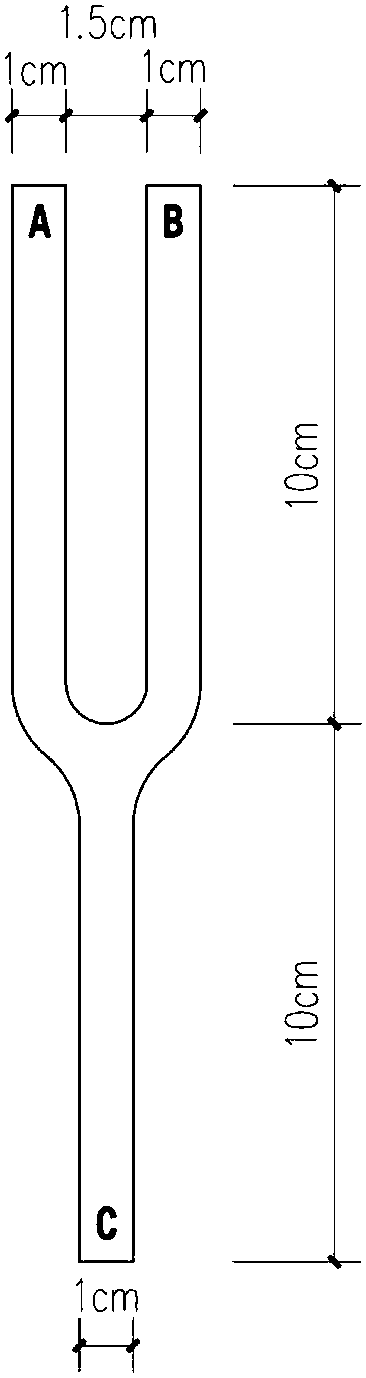
[0018] (1) At first prepare a mold fixed to the bracket, the mold is a longitudinal bar with parallel bifurcations; preferably, the ends with parallel bifurcations are respectively the A end and the B end, and the non-bifurcated end is the C end;

[0019] (2) Put the C side of the mold down and connect it to the bottom of the tensile machine, place the bracket between the A side and the B side of the mold, stick the bracket and the mold with 3M strong tape, and do not stick to the exposed ball The capsule is used to connect the bracket with the lower end of the tensile machine through the mould;

[0020] (3) Fix the catheter at the far end of the stent system to the top of the tension machine;

[0021] (4) Start the test, start the tensile testing machine to stretch until the stent moves relative to the balloon, record the maximum tensile value during this process as the stent removal force.


PUM


Abstract

The invention relates to a detection method for a removal force of a bracket system. The detection method comprises the following steps: (1) firstly, preparing a mold fixed with a bracket; (2) downward putting a non-forked end of the mold and connecting with the bottom end of a tension machine; putting the bracket between two parallel forked ends of the mold; sticking the bracket and the mold by utilizing a powerful sticky tape and connecting the bracket with the lower end of the tension machine through the mold; (3) fixing a guide pipe at a far end of the bracket system at the top end of thetension machine; (4) starting to test; starting a tension testing machine to stretch until the bracket moves relative to a balloon; recording a maximum pulling force value in the process as the bracket removal force. According to the detection method provided by the invention, the bracket and a clamp of the tension machine are connected by adopting the sticky tape so that the bracket and the clampare stuck by the sticky tape at the same time and are connected with each other; axial tension is provided by utilizing viscosity and a radial deformation force is not generated.

Description

technical field [0001] The invention relates to the field of medical technology, in particular to a method for detecting the removal force of a stent system. Background technique [0002] The coated stent is fixed on the catheter balloon through the crimping process. The indwelling force of the stent on the balloon is an important parameter to evaluate the crimping performance. Small, the stent has the risk of being unloaded after entering the human body, which will seriously affect the life safety of the patient. Therefore, it is necessary to test the retention force of the stent. The traditional test method uses a hard mold to withstand one end of the stent, and the stent is pushed out of the balloon when the tensile testing machine is stretched. This method is likely to cause deformation of the stent, easily cause measurement errors, and seriously lead to measurement failure. Contents of the invention [0003] The invention provides a method for detecting the removal ...

Claims


Application Information

Patent Timeline
IPC IPC(8): G01N19/04
CPCG01N19/04
Inventor 束晓文
Owner SUZHOU HUAN CHEN MEDICAL CO
Why Eureka
Try Eureka