Stamping part

A technology of parts and components, applied in the direction of pushing out equipment, etc., can solve the problems of large drop height and workpiece deformation, and achieve the effect of small drop height, uniform force and large coverage area.

Active Publication Date: 2019-05-21
安徽中瑞机床制造有限公司
View PDF12 Cites 0 Cited by
  • Summary
  • Abstract
  • Description
  • Claims
  • Application Information

AI Technical Summary

Problems solved by technology

[0006] Aiming at the problem that the existing stamping equipment uses a punching rod to beat the material, the workpiece falls out of the mold cavity, and the falling height is large, and the workpiece is easily deformed when it hits the lower mold after falling. Assemblies and the lower mold, the bottom of the mold base is equipped with an oil cylinder feeding device, and the upper mold assembly is equipped with a floating ejector assembly that can float up and down. The floating ejector assembly is pushed down by the oil cylinder feeding device to move the workpiece from the upper mold. The core groove of the component is ejected, which can make the workpiece separate from the upper die assembly at the same time as the upper die assembly returns. The falling height of the workpiece is small and will not cause deformation of the workpiece, which greatly improves the punching quality and yield

Method used


Image

  • Stamping part
  • Stamping part
  • Stamping part

Examples


Embodiment 1

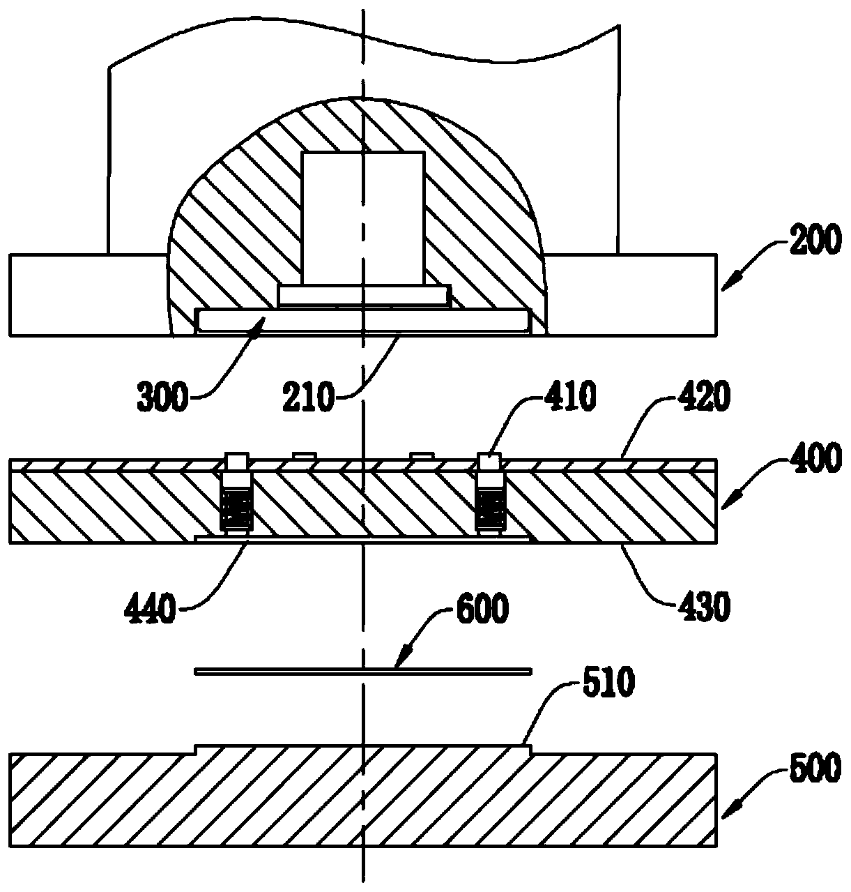
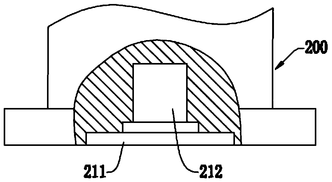
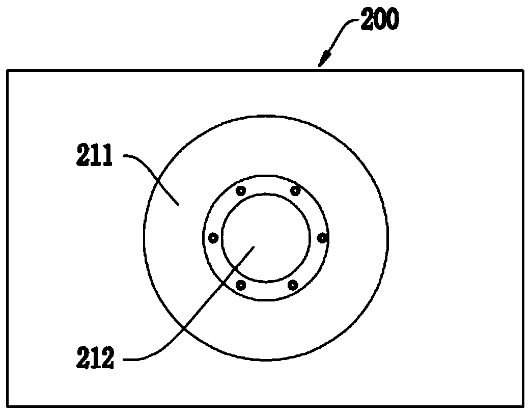
[0039] A stamped part such as figure 1As shown, the stamping part has: a die base 200, which is installed on a punch press and driven to move up and down by the punch press; an upper mold assembly 400, which is fixed on the bottom of the die base 200, moves with the die base 200, and moves up and down. The mold assembly 400 is detachably connected to the mold base 200 by bolts; the lower mold 500 is fixed on the punch press and is positioned on the mounting platform below the upper mold assembly 400, and cooperates with the upper mold assembly 400 up and down, and the lower mold 500 is detachably connected to the installation platform by bolts; the bottom of the mold base 200 is provided with an oil cylinder feeding device 300, and the upper mold assembly 400 is provided with a floating ejector assembly 410 that can float up and down, and the oil cylinder feeding device 300 against the upper end of the floating mandrel assembly 410, the lower end of the floating mandrel assemb...

Embodiment 2

[0044] A stamping part of this embodiment, the basic structure is the same as that of embodiment 1, the differences and improvements are as follows: Figure 4 As shown, the oil cylinder feeding device 300 includes an oil cylinder 310 and a material stripping plate 320, the oil cylinder 310 is fixed upside down on the bottom of the mold base 200, and is connected with the bottom of the mold base 200 by bolts, and the stripping plate 320 is fixed on The end of the piston rod 311 of the oil cylinder 310 is driven by the piston rod 311 to move the stripping plate 320 up and down.

[0045] After the oil cylinder 310 is started, the piston rod 311 stretches out to drive the stripper plate 320 to move downward, and the bottom of the stripper plate 320 bears against the upper end of the floating ejector rod assembly 410, making it move into the mold core groove 440, and the workpiece 600 is removed from the mold. The core groove 440 is ejected to achieve the purpose of separating the ...

Embodiment 3

[0048] A stamping part of this embodiment, the basic structure is the same as that of embodiment 2, the differences and improvements are as follows: figure 1 As shown, the bottom of the mold base 200 is provided with an installation groove 210, and the oil cylinder beating device 300 is arranged in the installation groove 210, so as to make room for the installation position of the upper mold assembly 400.

[0049] The installation groove 210 is a cylindrical straight groove or a stepped groove. In this embodiment, the installation groove 210 is a cylindrical straight groove with a uniform inner diameter along its axis, which is easy to process.

[0050] During the blanking process, the oil cylinder 310 is started, and the piston rod 311 is stretched out to push the stripper plate 320 out of the installation groove 210, and the stripper plate 320 moves against the floating ejector rod assembly 410, pushing the workpiece 600 out of the mold core groove 440 Then control the pist...


PUM

PropertyMeasurementUnit
thicknessaaaaaaaaaa
areaaaaaaaaaaa

Abstract

The invention discloses a stamping part, and belongs to the technical field of stamping devices. The stamping part comprises a die holder, an upper die assembly and a lower die. The die holder is driven to move up and down. The upper die assembly is fixed to the bottom of the die holder and moves along with the die holder. The lower die is arranged below the upper die assembly and cooperates withthe upper die assembly in the up-and-down direction. An oil cylinder material hitting device is arranged at the bottom of the die holder. Floating ejector rod assemblies which can float up and down are arranged in the upper die assembly. The oil cylinder material hitting device abuts against the upper ends of the floating ejector rod assemblies in a push mode, the lower ends of the floating ejector rod assemblies stretch into a die core groove formed in the bottom of the upper die assembly, and the floating ejector rod assemblies are driven by the oil cylinder material hitting device. According to the stamping part, the floating ejector rod assemblies are pushed by the oil cylinder material hitting device to move downwards, a workpiece is pushed out of the die core groove of the upper dieassembly, and therefore the workpiece can be separated from the upper die assembly as the return stroke of the upper die assembly is conducted, the workpiece falling height is small, the workpiece deformation cannot be caused, and the blanking quality and the yield are greatly improved.

Description

technical field [0001] The invention relates to the technical field of stamping devices, in particular to a stamping component. Background technique [0002] Punching is a stamping process that uses a die to separate part of the material or process part from another part of the material, process (process) part or waste. Blanking is a general term for the separation processes such as shearing, blanking, punching, punching, notching, sectioning, chiseling, edge trimming, tongue cutting, cutting, and trimming, and it accounts for the largest proportion in stamping production. In the blanking process, the sheet metal is sheared and deformed along a certain contour line by using the cutting edge of the die and separated. Except for the metal near the shear contour line, the sheet itself does not produce plastic deformation, so it is punched by a flat plate. The processed parts are still in a flat shape. [0003] Existing stamping equipment generally pushes the punched and forme...

Claims


Application Information

Patent Timeline
Patent Type & Authority Applications(China)
IPC IPC(8): B21D28/02B21D45/04
Inventor 夏尧林戴庆
Owner 安徽中瑞机床制造有限公司
Why Eureka
Try Eureka