Quick-change locking mechanism for power battery

A locking mechanism and power battery technology, which is applied in the direction of power devices, electric power devices, battery/battery traction, etc., can solve the problems of complex structure and complex operation of the locking mechanism, so as to improve NVH performance and reduce impact load , the effect of axial height reduction

Active Publication Date: 2021-01-29
DONGFENG MOTOR CORP HUBEI
View PDF19 Cites 2 Cited by
  • Summary
  • Abstract
  • Description
  • Claims
  • Application Information

AI Technical Summary

Problems solved by technology

This solution realizes locking and separation by controlling the state of the card bead in the limit groove, and its locking mechanism has complex structure and complex operation

Method used


Image

  • Quick-change locking mechanism for power battery
  • Quick-change locking mechanism for power battery
  • Quick-change locking mechanism for power battery

Examples


Embodiment Construction

[0035]In order to have a clearer understanding of the technical features, objectives and effects of the present invention, the specific embodiments of the present invention will now be described in detail with reference to the accompanying drawings.

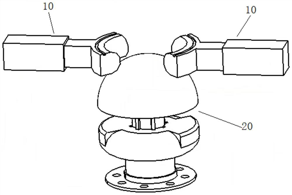
[0036]Such asfigure 1 As shown, a power battery quick-change locking mechanism provided by an embodiment of the present invention includes a fixing assembly 10 and a locking assembly 20.

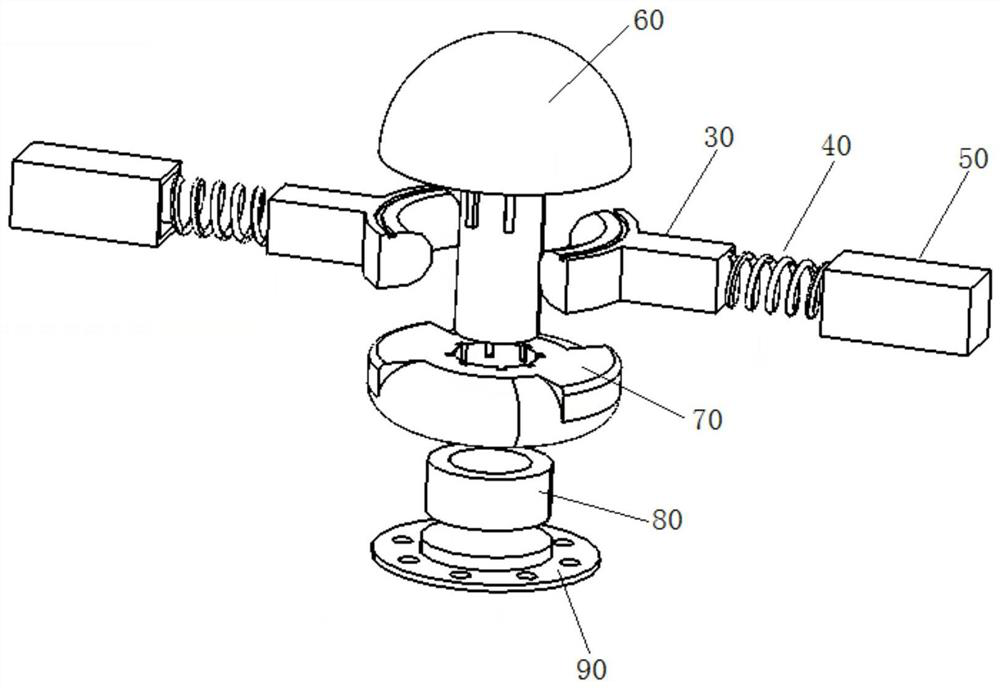
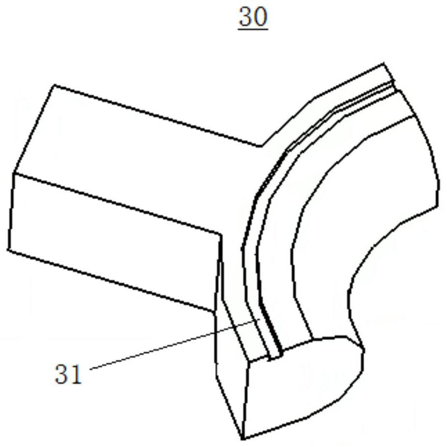
[0037]Such asfigure 2 As shown, the fixing assembly 10 includes a push rod 30, a first elastic member 40 and a fixing block 50. The fixed block 50 is a hollow structure with one end open, and is fixedly connected to the vehicle body longitudinal beam; one end of the push rod 30 is inserted into the fixed block 50, the first elastic member 40 is located between the push rod 30 and the fixed block 50, and the first elastic member 40 The two ends are respectively connected with the push rod 30 and the fixed block 50. Such asimage 3 As shown, the push rod 30 i...


PUM


Abstract

The invention relates to a quick-change locking mechanism for a power battery. The quick-change locking mechanism comprises a fixing assembly and a locking assembly, wherein the fixing assembly comprises a push rod, a first elastic piece and a fixing block; s groove is formed in the upper surface of the end, close to the locking assembly, of the push rod; the locking assembly comprises a locking shaft and a sliding block; the locking shaft comprises a hemispheroid and a cylindrical shaft which are coaxially arranged; the sliding block is sleeved on the cylindrical shaft and is provided with ahorizontal table board and a cambered surface which form an angle with each other; in a locking state, the push rod is respectively clamped with the horizontal table top and a lower surface of the hemispheroid, and a lower edge of the hemispheroid is clamped in the groove of the push rod; in the separation state, the arc surface makes contact with the push rod, and the push rod slides on the arc surface to achieve separation. The mechanism is advantaged in that installation reliability of the locking mechanism can be improved, and the occupied space of the locking mechanism can be reduced through a simple structure.

Description

Technical field[0001]The invention relates to the technical field of battery replacement for electric vehicles, and in particular to a quick locking mechanism for a power battery box and a vehicle body.Background technique[0002]At present, the charging time of electric vehicles is too long compared with the refueling time of traditional fuel vehicles, so there is the problem of electric vehicle cruising range anxiety. The industry is developing fast replacement technology for power battery packs, especially for operating vehicle users, which can greatly shorten the charging time.[0003]The Chinese patent with publication number CN109624779A discloses an automobile battery replacement device and an electric vehicle. The battery is locked by the sliders on both sides that are inserted into the pin slots of the pins, and the gravity of the battery pack and the slider are released from the pins on the pins. The card slot realizes battery unloading. In this solution, the push rod 5 needs ...

Claims


Application Information

Patent Timeline
Patent Type & Authority Applications(China)
IPC IPC(8): B60L53/80B60K1/04B60L50/60
CPCB60L53/80B60K1/04B60L50/66B60K2001/0455Y02T10/70Y02T10/7072
Inventor 周坤肖寒刘爽黄红波朱立宾
Owner DONGFENG MOTOR CORP HUBEI
Why Eureka
Try Eureka