Lens module and optical device

A lens module and optical device technology, applied in the field of lenses, can solve the problems of high geometric size requirements, disadvantageous lens module size reduction and assembly operations, and a large number of mechanism components, and achieves simple and fast assembly, simple mechanism design, and components. small number of effects

Active Publication Date: 2018-08-24
QISDA OPTRONICS (SUZHOU) CO LTD +1
View PDF6 Cites 0 Cited by
  • Summary
  • Abstract
  • Description
  • Claims
  • Application Information

AI Technical Summary

Problems solved by technology

The above method requires a large number of mechanical components, and in order to ensure that the lens can be moved smoothly and not leaked, the geomet

Method used


Image

  • Lens module and optical device
  • Lens module and optical device
  • Lens module and optical device

Examples


Example Embodiment

[0031] In order to have a further understanding of the purpose, structure, features, and functions of the present invention, the following detailed descriptions are provided in conjunction with the embodiments.

[0032] Certain words are used in the specification and claims to refer to specific elements. Those with general knowledge in the field should understand that manufacturers may use different terms to refer to the same component. This specification and claims do not use differences in names as a way to distinguish elements, but use differences in functions of elements as a criterion for distinguishing. The "including" mentioned in the entire specification and claims is an open term, so it should be interpreted as "including but not limited to".
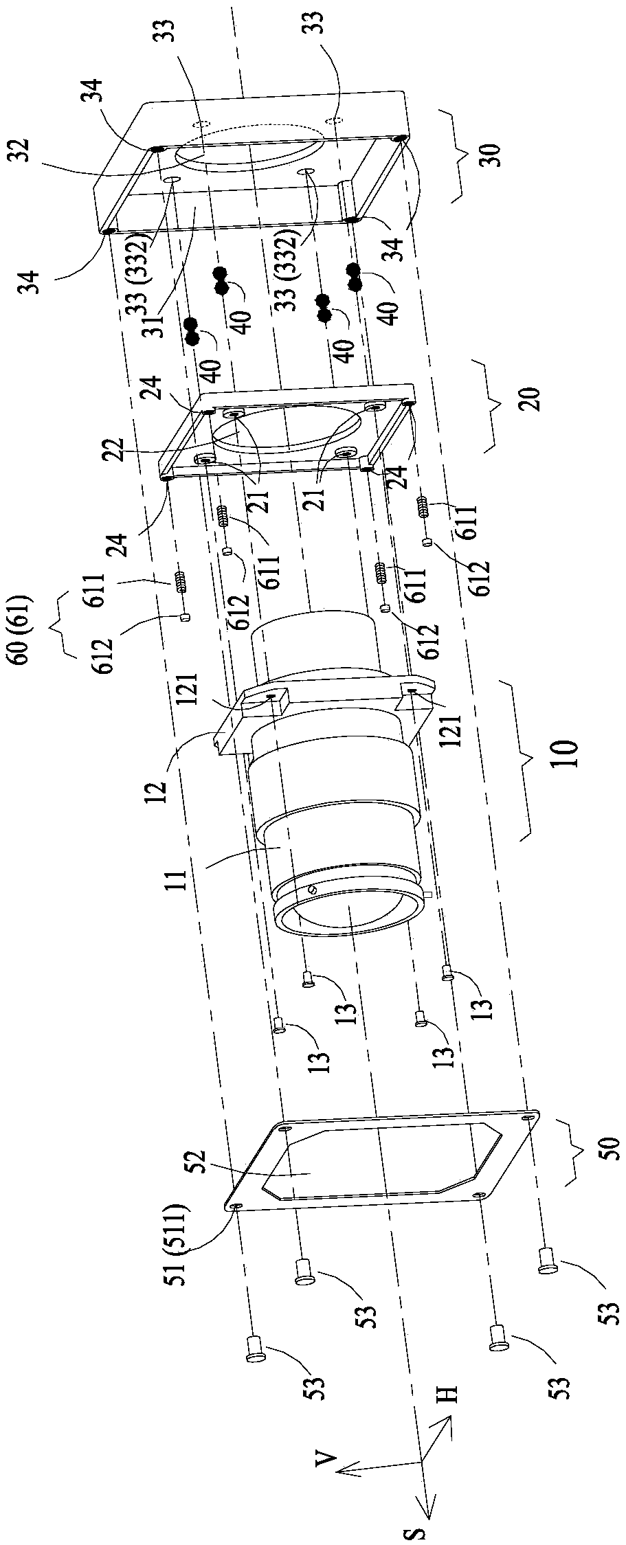
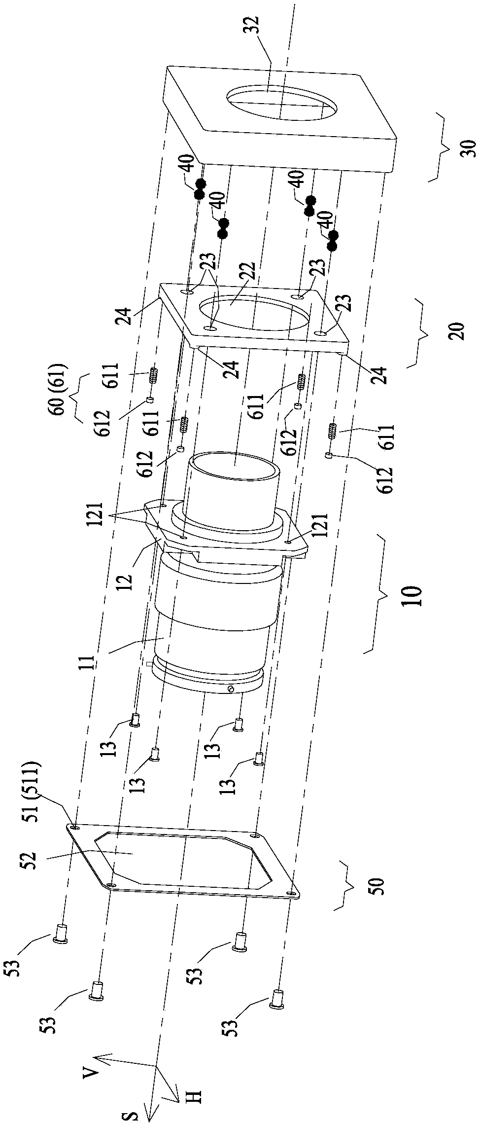
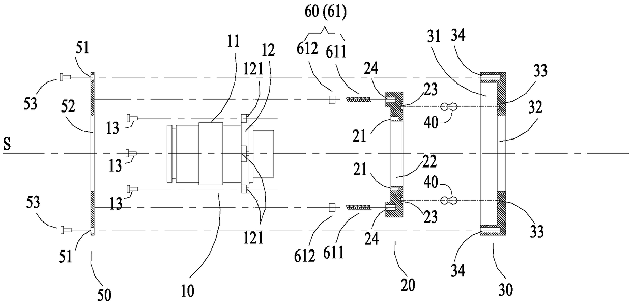
[0033] Reference Figure 1A to Figure 4C As shown, a schematic structural diagram of an embodiment of the lens module of the present invention is disclosed.

[0034] The lens module can be applied to optical devices that require opt...


PUM


Abstract

The invention provides a lens module, and the lens module comprises a lens, a moving member which is used for installing the lens and driving the lens to move relative to an optical axis direction perpendicular to the lens, a fixing member for movably supporting the moving member, and connecting members which are rotatingly connected with the moving member and the fixing member. The connecting members are employed as the parts which limit the movement of the moving member, used for installing the lens, relative to the fixing member and the distance, thereby enabling the moving member for installing the lens to steadily move in any direction ini the plane perpendicular to the optical axis of the lens. The lens module employs the simple structure design, needs fewer parts, is small in size,is simple and quick in assembly, and facilitates the popularization and application of optical devices in various sizes.

Description

technical field [0001] The invention relates to the lens field, in particular to a lens module with a movable lens and an optical device using the lens module. Background technique [0002] In an optical device, such as a projector, it is necessary to move the lens in the horizontal and vertical directions perpendicular to the optical axis. The current implementation method mainly includes: designing multiple base platforms, wherein the first one of the horizontal base and the vertical base is mounted on a fixed base, and the second base is mounted on the first base , it is necessary to design a mobile coupling structure in two directions, and the movement in two directions needs to be controlled by two handles respectively. The above method requires a large number of mechanical components, and in order to ensure that the lens can be moved smoothly and not leaked, the geometric dimensions of each component and assembly are relatively high, which is not conducive to the size...

Claims


Application Information

Patent Timeline
IPC IPC(8): G02B7/02G03B21/14
CPCG02B7/023G03B21/142
Inventor 彭伟钧何文中
Owner QISDA OPTRONICS (SUZHOU) CO LTD
Why Eureka
Try Eureka