Chute-type furnace roof distributor driven via self-centering combined link rod

A distributor and chute technology, which is applied in the field of blast furnace distributing devices, can solve the problems of affecting the quality and life, popularizing and applying, shortening the life, and aggravating the wear of the supporting ring.

Inactive Publication Date: 2005-07-06
李玉清
View PDF0 Cites 0 Cited by
  • Summary
  • Abstract
  • Description
  • Claims
  • Application Information

AI Technical Summary

Problems solved by technology

The α-angle drive mechanism driven by a set of double cranks driven by its offset drive shaft causes an insurmountable radial component force to the lower slewing bearing and its supporting ring, which makes the supporting ring wear more during operation and causes excessive wear. Early loss of balance of horizontal forces
As a result, the life is greatly shortened, which is the Achilles' heel that affects the quality, life and popularization and application of the current technology.

Method used


Image

  • Chute-type furnace roof distributor driven via self-centering combined link rod
  • Chute-type furnace roof distributor driven via self-centering combined link rod
  • Chute-type furnace roof distributor driven via self-centering combined link rod

Examples


Embodiment Construction

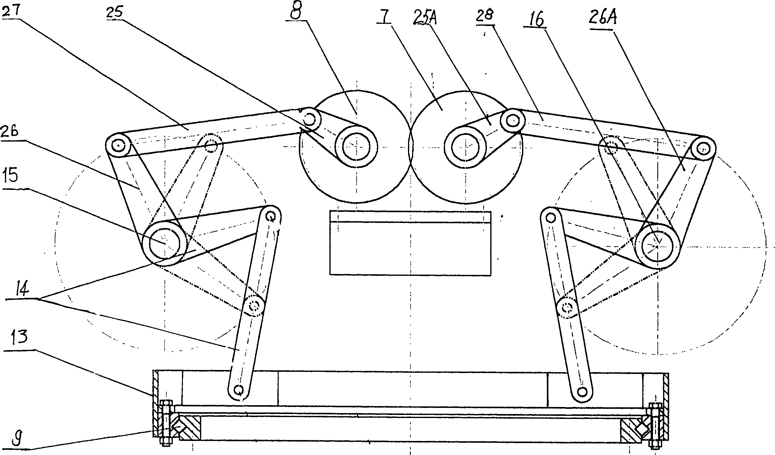
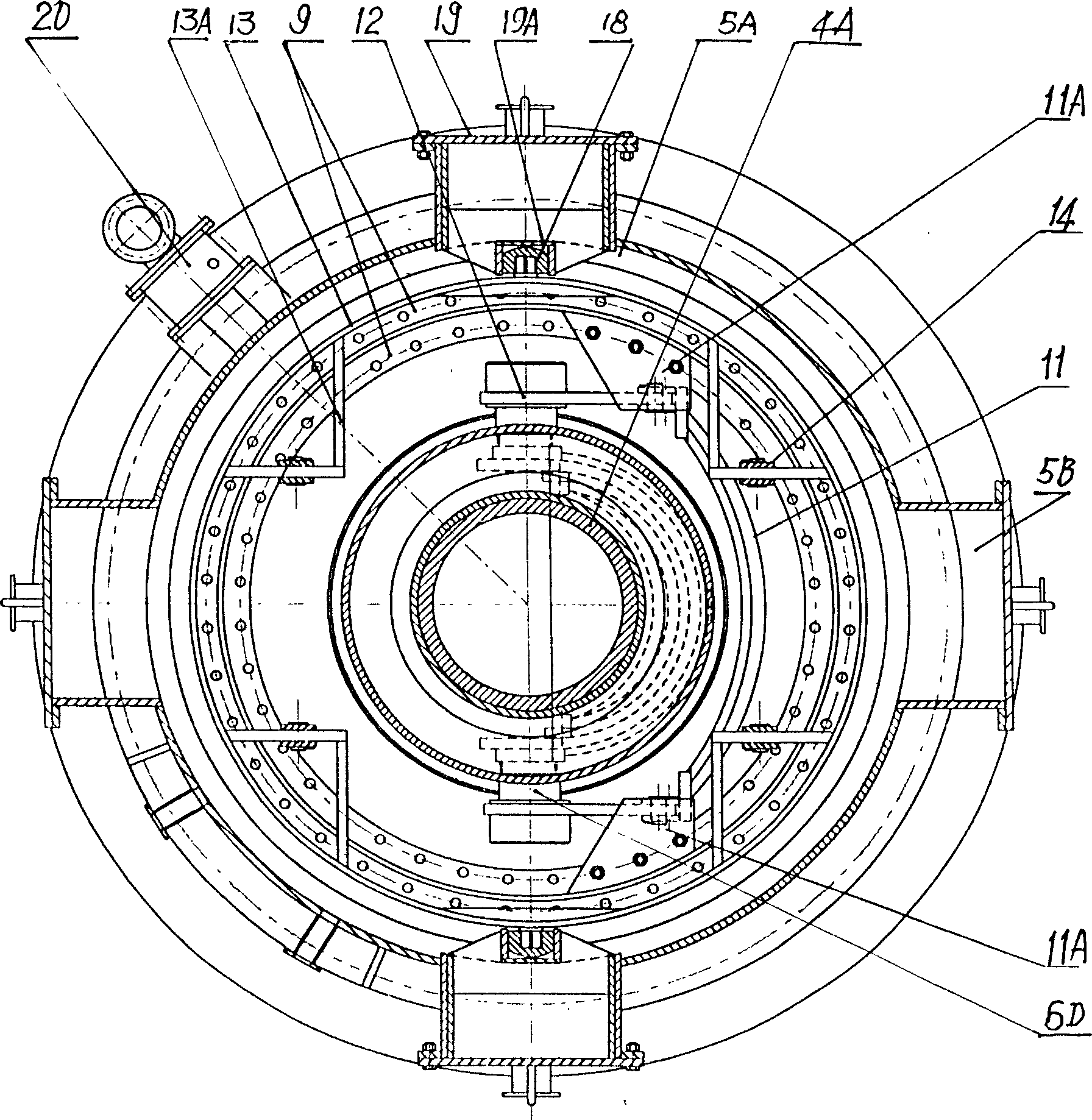
[0015] What the α angle transmission mechanism adopted in this device is by two shafts (15, 16) with opposite directions of rotation and four crank connecting rods (14) groups that are connected on the shaft and are symmetrically distributed. These four crank connecting rods are evenly connected on the outer support ring 13 of the upper bearing large support ring 9 . In this way, along with the synchronous rotation of the axles (15, 16), the four crank linkages form a synchronous self-centering grabbing mechanism. Grab and carry middle and lower bearing bearing support ring 9 and move up and down, but do not hinder the rotation of inner sleeve.

[0016] As long as the shafts 15 and 16 are synchronously and reversely rotated, the α-angle rotation mechanism can smoothly transmit the rotational torque to the symmetrical semi Shaft 6D, so that the chute can be driven by 6D to swing at an angle of α between 0° and 90°.

[0017] One of the keys of the above transmission is to ensu...


PUM


Abstract

The invention relates to the improvement of the structure of the chute-type distributor on the top of the blast furnace. The improved design includes four sets of symmetrical crank-connecting rods driven by the same mechanism to form a self-centering grabbing lifting mechanism as the α angle. The drive system adopts a ladder-shaped upper cover designed to prevent roof collapse and deformation, and a two-layer water-sealed airtight groove structure to prevent gas leakage at the top of the furnace, and is equipped with an anti-pressure safety device, which fundamentally overcomes the existing chute-type distribution It is a major improvement to the bellless furnace top technology.

Description

technical field [0001] The invention belongs to a blast furnace distributing device in metallurgical equipment, in particular to an improved design of a chute type distributing device. Background technique [0002] The blast furnace is the basic equipment in the metallurgical industry. Iron ore and coke are loaded into the blast furnace, and pig iron can be produced by smelting after blowing in oxygen. The construction of the blast furnace costs hundreds of millions of yuan and adopts continuous production operations. Coke and ore are continuously added from the top of the furnace, and the cloth is layered and spaced. The more uniform the distribution, the better the effect, less consumables, high output and good quality of molten iron. Since gas is the main by-product of the blast furnace, and the blast furnace must maintain a high temperature and high pressure state during the smelting process, the feeding must be carried out in an airtight state. The larger the furnace, ...

Claims


Application Information

Patent Timeline
Patent Type & Authority Patents(China)
IPC IPC(8): C21B7/20
Inventor 李玉清
Owner 李玉清
Why Eureka
Try Eureka