Object pose estimation method, device and electronic equipment
A pose estimation, object technology, applied in computing, computer parts, image data processing, etc., can solve the problem of accuracy and confidence not being improved.
- Summary
- Abstract
- Description
- Claims
- Application Information
AI Technical Summary
Problems solved by technology
Method used
Image
Examples
Embodiment 1
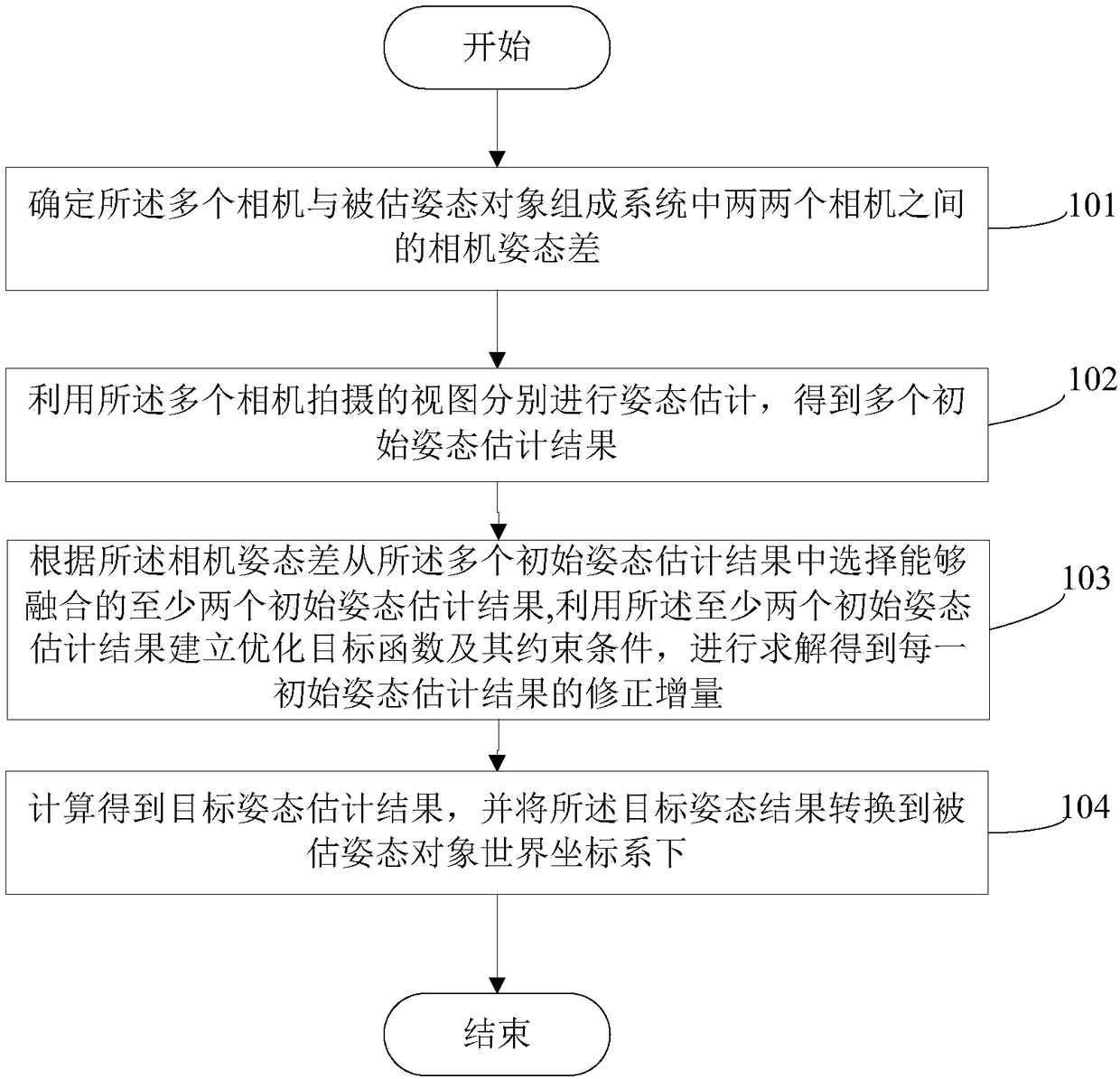
[0104] This embodiment provides a method for estimating the pose of an object. Multiple cameras are used to perform pose estimation on the same object with an estimated pose. The multiple cameras can capture views of the object with an estimated pose from different perspectives. The estimated pose object areas captured by the cameras associated with each other in two cameras have overlapping parts, such as figure 1 As shown, the method includes:
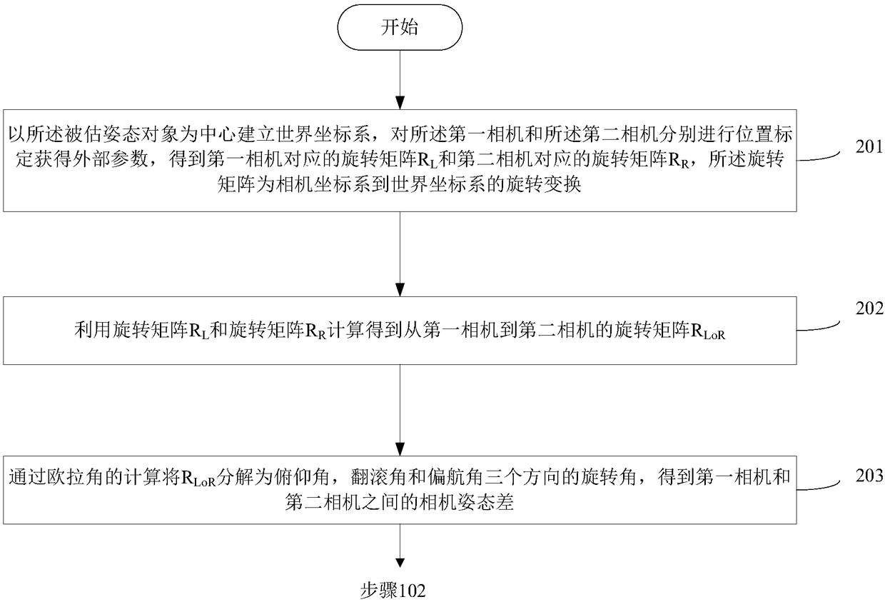
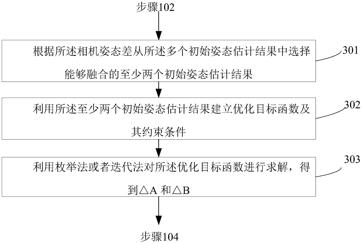
[0105] Step 101: Determine the camera attitude difference between two cameras in the system composed of the plurality of cameras and the estimated attitude object, and the camera attitude difference is the difference between the attitude results obtained for the same estimated attitude object from different camera visual angles. The fixed difference is equivalent to the rotation angle from one camera to another camera along three orthogonal directions in the world coordinate system, and the estimated pose object regions captured by t...
Embodiment 2
[0142] This embodiment provides a device for estimating the pose of an object. Multiple cameras are used to perform pose estimation on the same object with an estimated pose. The estimated pose object areas captured by the cameras associated with each other in two cameras have overlapping parts, such as Figure 4 As shown, the device includes:
[0143] The camera attitude difference determination module 41 is used to determine the camera attitude difference between two cameras in the system composed of the plurality of cameras and the estimated attitude object, and the camera attitude difference is obtained from different camera visual angles for the same estimated attitude object The fixed difference between the resulting attitude results is equivalent to the rotation angle from one camera to another camera along three orthogonal directions in the world coordinate system, and the estimated attitude object areas captured by the two cameras respectively have overlapping parts;...
Embodiment 3
[0180] This embodiment also provides an electronic device for estimating the pose of an object. Multiple cameras are used to perform pose estimation on the same object with an estimated pose. The multiple cameras can capture views of the object with an estimated pose from different angles of view, and the Among the plurality of cameras, the estimated pose object areas captured by the pairwise associated cameras have overlapping parts, such as Figure 7 As shown, the electronic device 60 includes:
[0181] processor 62; and
[0182] a memory 64 in which computer program instructions are stored,
[0183] Wherein, when the computer program instructions are executed by the processor, the processor 62 is made to perform the following steps:
[0184] Determining the camera attitude difference between two cameras in the system composed of the plurality of cameras and the estimated attitude object, the camera attitude difference is the fixed difference between the attitude results o...
PUM
 Abstract
Description
Claims
Application Information
 - R&D
- Intellectual Property
- Life Sciences
- Materials
- Tech Scout
- Unparalleled Data Quality
- Higher Quality Content
- 60% Fewer Hallucinations
Browse by: Latest US Patents, China's latest patents, Technical Efficacy Thesaurus, Application Domain, Technology Topic, Popular Technical Reports.
© 2025 PatSnap. All rights reserved.Legal|Privacy policy|Modern Slavery Act Transparency Statement|Sitemap|About US| Contact US: help@patsnap.com


