Externally inflatable type transient electromagnetic transmitting and receiving antenna

A transient electromagnetic and receiving antenna technology, applied in the direction of inflatable antennas, antennas, folding antennas, etc., can solve the problems that the support structure cannot be a metal dielectric structure, inconvenient construction work, and narrow working space, so as to achieve enhanced rigidity and easy portability , Improve the effect of rigidity and stability

Active Publication Date: 2018-08-24
山东百廿慧通工程科技有限公司
View PDF9 Cites 4 Cited by
  • Summary
  • Abstract
  • Description
  • Claims
  • Application Information

AI Technical Summary

Problems solved by technology

[0003] At present, the commonly used coil carrying devices are wooden materials or plastic composite materials. This kind of device has heavy structural quality, is not easy to carry, and is difficult to operate; because the transient electromagnetic method uses the transmitting coil to energize and emit a pulse magnetic field, the receiving coil receives the induction ground. Therefore, the supporting structure cannot be a metal dielectric structure; when tunnels and mines are used for transient electromagnetics, the working space is narrow, and it is inconvenient to use wood or plastic composite materials for construction and operation, and the itself is heavy; the coil area carried by aviation transient electromagnetics is large and must be A material with high strength, light weight, good stability is used as the coil mounting device

Method used


Image

  • Externally inflatable type transient electromagnetic transmitting and receiving antenna
  • Externally inflatable type transient electromagnetic transmitting and receiving antenna
  • Externally inflatable type transient electromagnetic transmitting and receiving antenna

Examples


Embodiment Construction

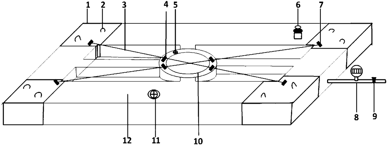
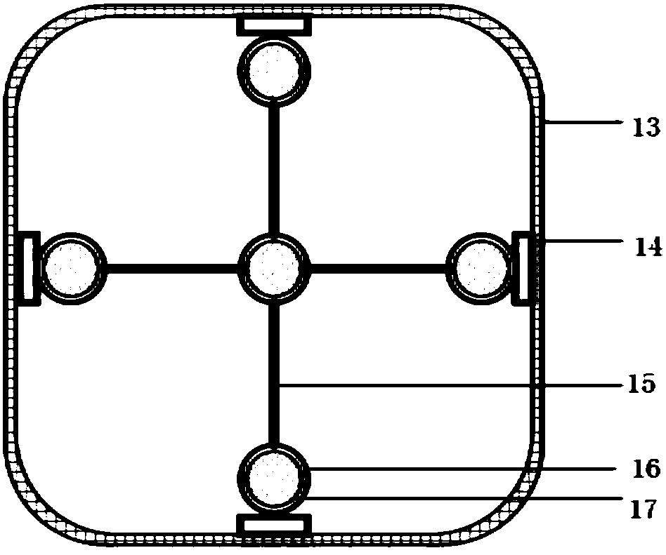
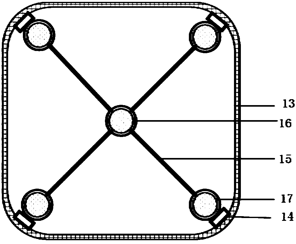
[0035] The present invention will be further described below in conjunction with the accompanying drawings and embodiments.

[0036] It should be pointed out that the following detailed description is exemplary and intended to provide further explanation to the present application. Unless defined otherwise, all technical and scientific terms used herein have the same meaning as commonly understood by one of ordinary skill in the art to which this application belongs.

[0037] It should be noted that the terminology used here is only for describing specific implementations, and is not intended to limit the exemplary implementations according to the present application. As used herein, unless the context clearly dictates otherwise, the singular is intended to include the plural, and it should also be understood that when the terms "comprising" and / or "comprising" are used in this specification, they mean There are features, steps, operations, means, components and / or combinatio...


PUM


Abstract

The invention discloses an externally inflatable type transient electromagnetic transmitting and receiving antenna. The antenna comprises a supporting frame with a communicated air passage. The air passage in the supporting frame is controlled by an air valve, and a pressure gauge is arranged at an inlet of the air passage. Receiving/ transmitting antenna external connectors are arranged outside the supporting frame. Each external connector is correspondingly connected with a receiving/ transmitting antenna arranged in the air passage. An elastic safety valve is arranged on the outer surface of the supporting frame. The supporting frame can be quickly expanded to realize the supporting effect through the inflating effect, so that the transient electromagnetic receiving and transmitting antenna is in a normal working state. According to the invention, the air thermal expansion effect is introduced, and the receiving/ transmitting antenna is arranged in the air passage. Due to the fact that a coil can generate heat during working, the temperature in the air passage rises. Meanwhile, the volume of the air is increased. As a result, the safety valve installed in the air passage is usedfor stabilizing the internal pressure of the air passage.

Description

technical field [0001] The invention relates to an external air-filled transient electromagnetic transmitting and receiving antenna. Background technique [0002] Transient electromagnetic is a time-domain artificial source electromagnetic detection method based on the principle of electromagnetic induction. Transient electromagnetic uses an ungrounded return line or a grounded line source to send a pulsed magnetic field underground, and the induced eddy current excited in the underground geological body under its excitation will generate an induced electromagnetic field that changes with time to reflect the structure of the underground geological body Information, this method is used in the fields of engineering geological exploration and resource exploration. [0003] At present, the commonly used coil carrying devices are wooden materials or plastic composite materials. This kind of device has heavy structural quality, is not easy to carry, and is difficult to operate; b...

Claims


Application Information

Patent Timeline
Patent Type & Authority Applications(China)
IPC IPC(8): H01Q1/00H01Q1/08H01Q1/12H01Q1/36H01Q1/42H01Q1/50
CPCH01Q1/00H01Q1/081H01Q1/12H01Q1/36H01Q1/42H01Q1/50
Inventor 孙怀凤李阳阳张诺亚陈成栋刘翼飞李术才吴启龙
Owner 山东百廿慧通工程科技有限公司
Why Eureka
Try Eureka