Rail vibration energy collection device

A technology for collecting device and vibration energy, applied in the direction of generator/motor, piezoelectric effect/electrostrictive or magnetostrictive motor, electrical components, etc. Short service life and other problems, to achieve the effect of stable and reliable energy supply and reduce the risk of train operation

Inactive Publication Date: 2018-08-24
WUHAN UNIV OF TECH
View PDF7 Cites 5 Cited by
  • Summary
  • Abstract
  • Description
  • Claims
  • Application Information

AI Technical Summary

Problems solved by technology

However, the piezoelectric type has a short service life and low conversion efficiency, the electromagnetic type has a large size, and the

Method used


Image

  • Rail vibration energy collection device

Examples


Embodiment Construction

[0029] In order to make the object, technical solution and advantages of the present invention clearer, the present invention will be further described in detail below in conjunction with the accompanying drawings and embodiments. It should be understood that the specific embodiments described here are only used to explain the present invention, not to limit the present invention.

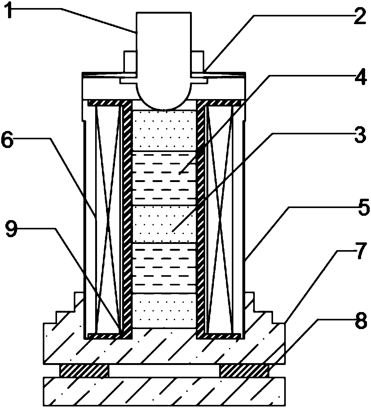
[0030] see figure 1 , a rail vibration energy collection device, which includes a housing 5, a vibration pickup mechanism 1, a coil bobbin 9, an induction coil 6, a permanent magnet unit, a giant magnetostrictive rod unit, a disc spring 2, and a base 7. The shell 5 is made of magnetically conductive material, placed between the gravel and the rail, which can perfectly utilize the vibration energy of the rail without destroying the original structure of the rail, and is convenient for construction. The vibration pickup mechanism 1 is placed on the top of the shell 5, and its lower end is a spherica...


PUM

PropertyMeasurementUnit
Heightaaaaaaaaaa

Abstract

The invention discloses a rail vibration energy collection device, comprising a shell, a vibration pickup mechanism, a coil skeleton, an induction coil, a permanent magnet unit, an ultra-magnetostriction rod unit and a pedestal. The shell is placed between gravels and a rail; the vibration pickup mechanism is placed at the top of the shell and the lower end is a spherical structure; the coil skeleton is placed in the shell; the induction coil is wound on the coil skeleton and is externally connected to a circuit through the shell; the permanent magnet unit includes three segments of cylindrical permanent magnets which are vertically arranged in the coil skeleton; the ultra-magnetostriction rod unit comprises two segments of cylindrical ultra-magnetostriction rods which are vertically arranged in the coil skeleton and among the cylindrical permanent magnets and separate the three segments of cylindrical permanent magnets; a disc spring is located at the upper side of the spherical structure of the vibration pickup mechanism and is fixed to the vibration pickup mechanism; and the pedestal is located at the bottom of the shell. The rail vibration energy collection device provided by the invention can collect vibration energy generated by the rail and convert the vibration energy into electric energy.

Description

technical field [0001] The invention relates to the technical field of self-harvesting energy collection, in particular to a rail vibration energy collection device. Background technique [0002] With the expansion of the scope of railway construction in our country, it is necessary to build tunnels in areas with complex terrain. At present, wired circuits and mobile terminals are mainly used at home and abroad to display the situation in railway tunnels. The circuits are easily affected by the outside world and cause monitoring blind spots in the tunnel, which brings safety hazards to trains. For most railway tunnels with complex terrain and remote areas, the problems of many detection nodes, difficult cable erection and high maintenance costs are difficult to solve through traditional energy supply systems. In this context, the collection of rail vibration energy has become a domestic A hot topic of research by foreign scholars. Existing vibration energy power generation...

Claims


Application Information

Patent Timeline
IPC IPC(8): H02N2/18
CPCH02N2/186
Inventor 肖祥何佳琛方正雷奇恒郭慧婧尹知昊余俊伟
Owner WUHAN UNIV OF TECH
Why Eureka
Try Eureka