
A High Voltage Converter System for Switched Reluctance Wind Power Generator

A wind turbine, switched reluctance technology, applied in the direction of controlling generators, controlling generators, and control systems through magnetic field changes, can solve the problem that the advantages of switched reluctance generators cannot be exerted, increase the possibility of damage to the switch tube, Increase the workload of manual maintenance and other problems to achieve the effect of simple structure, low cost and high reliability

Inactive Publication Date: 2019-07-30
CHINA JILIANG UNIV
View PDF7 Cites 0 Cited by
  • Summary
  • Abstract
  • Description
  • Claims
  • Application Information

AI Technical Summary

Problems solved by technology

[0005] The excitation and power generation of the switched reluctance generator must be realized around the operation control of the inverter circuit connected to its winding. Without the winding inverter circuit, the switched reluctance generator naturally has no meaning; Control the use of power electronic switching tubes, and in the application of these switching tubes, the switching loss, especially the switching loss of high-frequency switching operation, is a major research problem in the industry. Excessive switching loss causes a large loss of system power and low efficiency. And it increases the possibility of serious damage to the switch tube due to large loss and heat
[0006] Since the excitation stage is mainly to absorb electric energy, it is hoped that the excitation current can be established more quickly in a short time, that is, the excitation will be strengthened, so as to leave more time for the power generation stage and a larger initial current, and improve the power output capability. Based on this, the industry is currently It is often necessary to design a special excitation power supply to strengthen the excitation, but these enhanced excitation methods often need to be realized by adding a special excitation power supply with a controllable switch tube, which reduces the reliability of the system and increases the complexity of the control. When the excitation power supply fails, the entire switched reluctance generator will stop and cannot operate, so that the advantages of the switched reluctance generator with high fault-tolerant performance of power generation cannot be brought into play. If the excitation is strengthened inside the converter branch of each phase winding , then this problem does not exist; when it comes to excitation, it also involves the source of electric energy required for excitation. The industry is generally divided into self-excitation and external excitation. If self-excitation often cooperates with strengthening the excitation effect, it generally requires the design of a special excitation circuit. As mentioned above The disadvantages mentioned above are obvious. External incentives generally use batteries, which greatly increases the workload of manual maintenance.

Method used


Image

  • A High Voltage Converter System for Switched Reluctance Wind Power Generator
  • A High Voltage Converter System for Switched Reluctance Wind Power Generator

Examples


Embodiment Construction

[0023] The switched reluctance generator 2 of the present invention is coaxially connected with the excitation power supply, that is, the permanent magnet DC generator 3, and the switched reluctance generator 2 is connected with the wind turbine 1 coaxially or through a gearbox, as shown in the attached figure 1 shown.

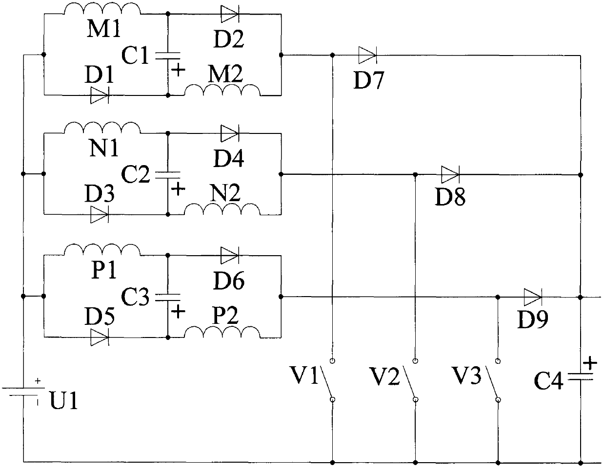
[0024] The switched reluctance generator 2 of this embodiment is a three-phase winding, which is respectively M / N / P three-phase windings according to the order distributed on the stator. Each phase winding is composed of two branch windings and is symmetrically wound on different stators. on a salient pole, as attached figure 2 Shown is the converter circuit of the three-phase winding switched reluctance wind power generator of this embodiment.

[0025] The high-voltage converter system of the switched reluctance wind power generator in this embodiment is composed of 9 diodes, 3 phase windings, 4 capacitors, 3 switching tubes, and 1 DC power supply. One end ...


PUM


Abstract

Disclosed is a high-voltage current conversion system of a switch reluctance wind power generator. A switch reluctance generator is used as a main wind power generator, and the output electric energyof a permanent magnet direct current generator coaxially connected with the switch reluctance generator is used as exciting electric energy of the switch reluctance generator; each phase of winding ofthe switch reluctance generator comprises two branches which are connected in parallel in excitation while in series in power generation, thereby strengthening the excitation effect; in power generation, the direct current power supply needed by excitation and a charged capacitor in excitation are both connected with the corresponding phase winding to be participated in power generation output, thereby highly improving the output voltage; and the whole current conversion system is high in expandability, high in reliability, simple in structure, easy to control, low in loss and suitable for medium-low-power wind power and medium-high-voltage direct current grid connection or direct current load power utilization fields.

Description

technical field [0001] The invention relates to the field of wind power generation, in particular to a switched reluctance wind power generator converter system and a control method thereof with a coaxial permanent magnet direct current generator as an excitation power supply, self-strengthened excitation, direct high voltage generation structure and easy control. Background technique [0002] The structure of the switched reluctance motor is simple and strong, the manufacturing cost is low, there are no windings on the rotor, no permanent magnets, and the reliability is high; when used as a generator, one of the phase windings does not work without affecting the power output of the other phase windings, and the fault tolerance is strong ,with broadly application foreground. [0003] In recent years, DC transmission has been increasingly valued by the power sector. Local DC power grids have begun to take shape in some places, and high-voltage DC transmission is also developi...

Claims


Application Information

Patent Timeline
Patent Type & Authority Patents(China)
IPC IPC(8): H02P9/38H02P9/30H02P101/15
CPCH02P9/305H02P9/38H02P2101/15
Inventor 孙冠群宋春伟郭倩
Owner CHINA JILIANG UNIV
Learn More