

Clamp for machine tool processing
A fixture and machine tool technology, which is applied in the direction of manufacturing tools, metal processing equipment, metal processing machinery parts, etc., can solve the problems of milling cutters to be processed, such as broken objects, economic losses, etc., to avoid economic losses, easy manufacturing, and ingenious design Effect
- Summary
- Abstract
- Description
- Claims
- Application Information
AI Technical Summary
Problems solved by technology
Method used
Image

Examples
Embodiment Construction
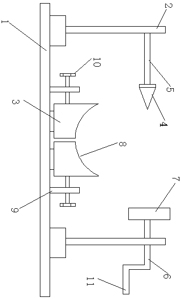
[0011] A fixture for machine tool processing, comprising a base plate 1, two brackets 2, and a pair of bases 3, the brackets are respectively placed on the left and right sides of the base plate, the upper part of the left bracket is provided with a fixed vertebral body 4, and the fixed vertebral body The body is connected to the left bracket through a connecting rod 5, the connecting rod is parallel to the bottom plate, and the tip of the fixed vertebral body points to the right; the upper part of the right bracket is threaded with an adjusting rod 6, and the end of the adjusting rod is provided with a flat plate 7. The flat plate and the fixed vertebral body are placed facing each other; a chute is arranged horizontally in the middle of the upper surface of the bottom plate, and a pair of bases are respectively slidably connected to the chute through sliders; the top of each base is provided with an arc-shaped notch 8, two arc The gaps are spliced to form a semicircle; the ...
PUM
 Abstract
Description
Claims
Application Information