
Textile manufacturing equipment

A textile and equipment technology, applied in the field of textile production equipment, can solve the problems of no installation, no shock absorption device, no anti-wrinkle device, etc., and achieve the effect of scientific and reasonable structure, safe and convenient use

Inactive Publication Date: 2018-08-28
海宁市华涛经编股份有限公司
View PDF5 Cites 14 Cited by
  • Summary
  • Abstract
  • Description
  • Claims
  • Application Information

AI Technical Summary

Benefits of technology

This new design helps prevent damage from flying or falling debris during fabrication processes that generate significant amounts of waste material (flies) on both human operators and machines themselves. It also includes an efficient way for removing this feature without causing any harm if it works properly.

Problems solved by technology

This patented technical problem addressed by this patents is that current textile manufacturing devices have multiple functions without any means or filters designed specifically towards reducing excessive noise caused from their operation while still maintaining smoothness over time.

Method used

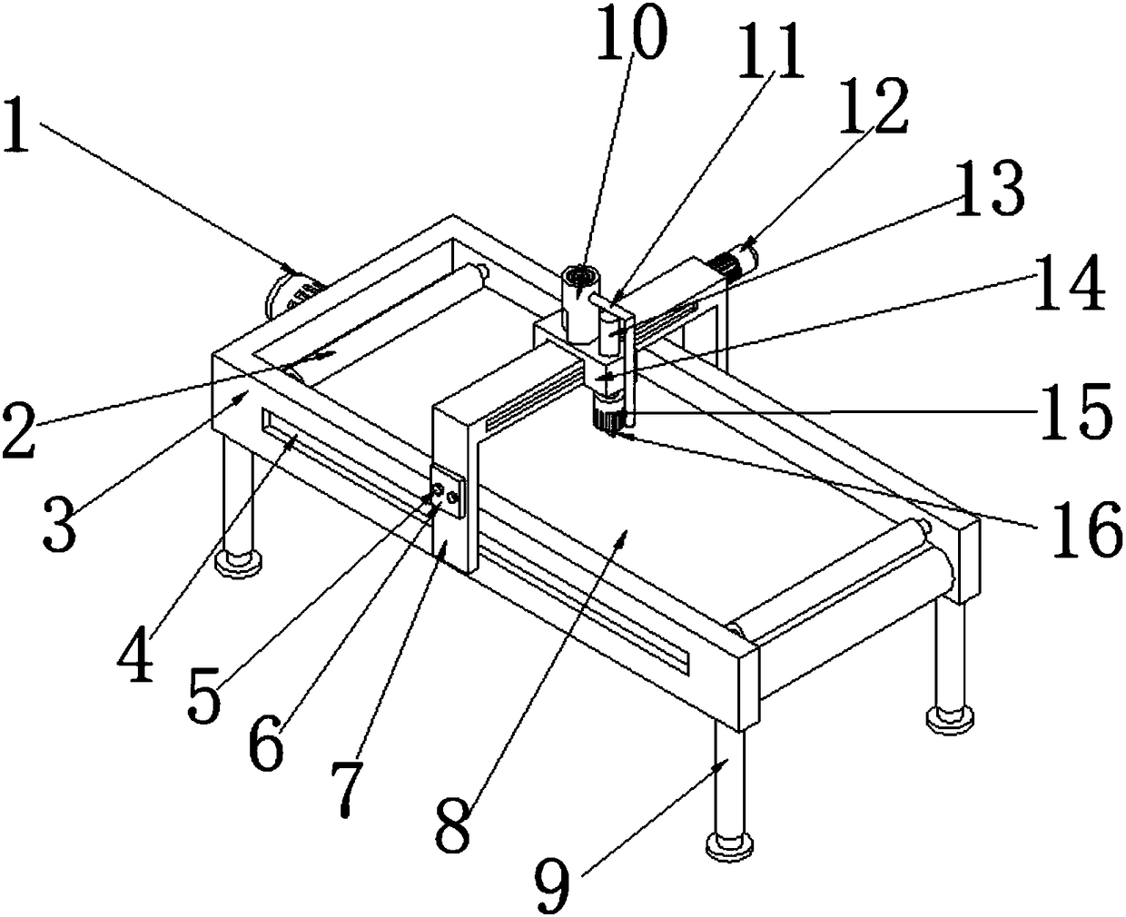

Image

  • Textile manufacturing equipment
  • Textile manufacturing equipment
  • Textile manufacturing equipment

Examples


Embodiment

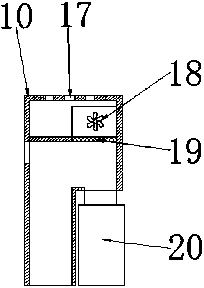
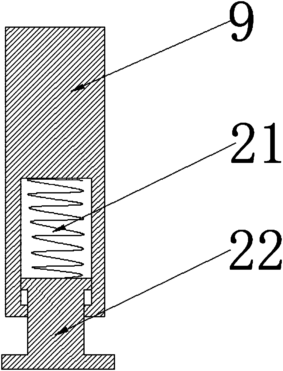
[0018] Example: such as Figure 1-3 As shown, the present invention provides a technical solution, a textile production equipment, including a first servo motor 1, a pressure roller 2, a frame 3, a slide rail 4, a control panel 5, an electric control box 6, a beam slide rail 7, Conveyor belt 8, bracket 9, housing 10, connecting pipe 11, second servo motor 12, electric push rod 13, slider 14, rotating motor 15, cutting knife 16, air outlet groove 17, fan 18, filter screen 19, ash storage Tank 20, spring 21 and support 22, a first servo motor 1 is arranged on one side of the frame 3, a conveyor belt 8 is arranged on the inner side of the first servo motor 1, and pressure rollers are arranged on the inner side of the first servo motor 1 and at both ends of the conveyor belt 8 2. Brackets 9 are provided around the bottom of the frame 3, slide rails 4 are provided on both sides of the frame 3, a crossbeam slide rail 7 is provided on one side of the slide rail 4, and an electric con...


PUM


Abstract

The invention discloses textile manufacturing equipment comprising a first servo motor, pressing rollers, a rack, a sliding rail, a sliding block, a rotary motor, a cutter, a gas outlet groove, a fan,a strainer, a dust storing tank, a spring and a support seat. The first servo motor is arranged on one side of the rack. A conveying belt is arranged on the inner side of the first servo motor. The textile manufacturing equipment is scientific and reasonable in structure and safe and convenient to use, a dust removing device is arranged, in the textile cutting process, a large amount of dust is generated, the production environment and the bodies of workers are influenced, and flying fabrics and dust generated in the cut position are collected and processed through the arranged dust removingdevice. A damping device is arranged, vibration of the textile manufacturing equipment is relieved and lowered effectively through the spring arranged on the inner side of the bottom of a support frame when the textile manufacturing equipment works, a crease-resist device is arranged, and textiles are pressed to be kept flat through the pressing rollers at a feed inlet and a discharge outlet in the cutting process.

Description


Claims


Application Information

Patent Timeline
Owner 海宁市华涛经编股份有限公司
Learn More