Automatic unloading device for rear-turning cars

An automatic unloading and vehicle technology, which is applied in the direction of vehicles with inclined bearing movement, etc., can solve the problems of easily damaged piston rods, inability to ensure support, unfavorable use, etc.

Active Publication Date: 2019-04-12
南通东东钢构有限公司
View PDF6 Cites 0 Cited by
  • Summary
  • Abstract
  • Description
  • Claims
  • Application Information

AI Technical Summary

Problems solved by technology

[0004] In the prior art, the dump truck needs to turn the carriage back, and usually first controls the movement of the piston rod to realize the back turn of the carriage. This method is easy to damage the piston rod during the backturn of the carriage, which is not conducive to long-term use, because the force is exerted during the backturn of the carriage. The point is generally at the angle between the carriage and the chassis, and the piston rod only provides upward thrust, which cannot guarantee that the support between the carriage and the chassis will not be broken due to uneven force during the backturning process of the carriage, causing the carriage to Slip and break the piston rod, causing an accident

Method used


Image

  • Automatic unloading device for rear-turning cars
  • Automatic unloading device for rear-turning cars
  • Automatic unloading device for rear-turning cars

Examples


Embodiment

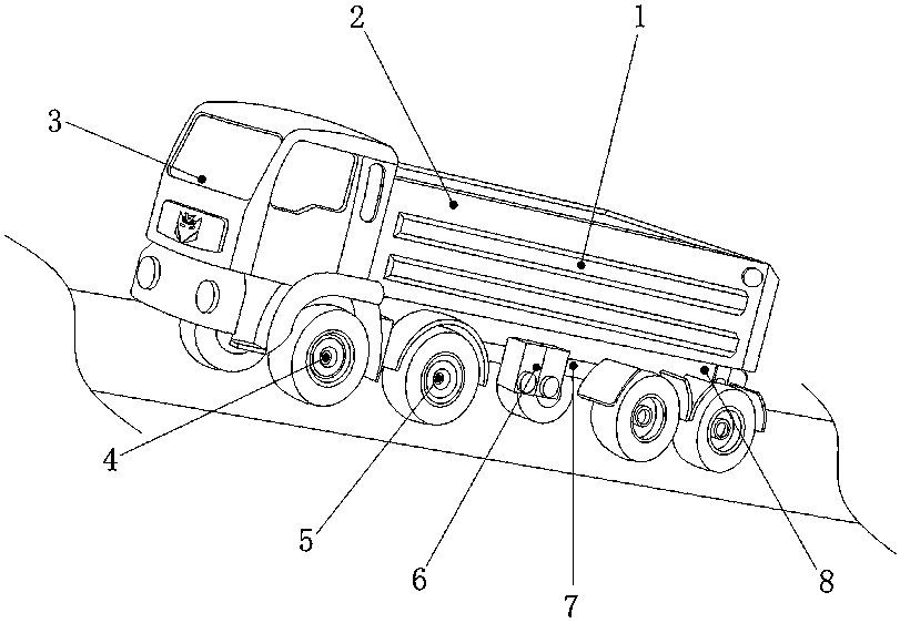
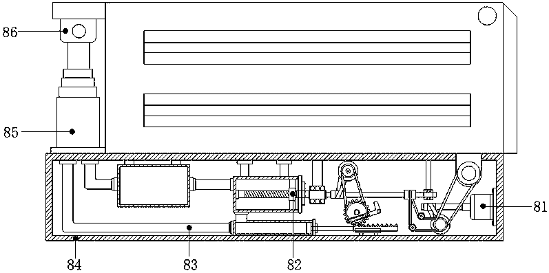
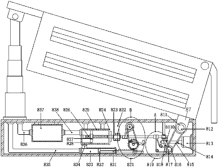
[0027] see Figure 1-Figure 5 , the present invention provides an automatic unloading device for a rear-turning car, the structure of which includes a hopper side reinforcement rib 1, a hopper 2, a driving control cabin 3, traction wheels 4, driven wheels 5, a fuel tank 6, a chassis 7, and an automatic unloading device 8, The bottom of the chassis 7 is equidistantly provided with six driven wheels 5, the driven wheels 5 and the chassis 7 adopt a clearance fit, and one side of the chassis 7 is provided with a fuel tank 6, and the two adopt an interference fit The front end of the chassis 7 is provided with a driving control cabin 3 and the two adopt a clearance fit, and the bottom of the driving control cabin 3 is evenly and equidistantly provided with two traction wheels 4, and the traction wheels 4 and the driving control cabin 3 Transmission connection, the fuel tank 6 is connected with the driving control cabin 3 through a conduit, the top of the chassis 7 is provided with ...


PUM


Abstract

The invention discloses an automatic unloading device for rear-tipping truck. The structure includes a hopper side rib, a hopper, a driving control cabin, a traction wheel, a driven wheel, a fuel tank, a chassis, and an automatic unloading device body. The top of the chassis is provided with an automatic unloading device body and the two are in interference fit. The top of the automatic unloadingdevice body is provided with a hopper and the two cooperate. The automatic unloading device body first controls the rotation of the rear-tipping circular shaft through an active mechanism provided inside the steel outer frame. As the rear turn round shaft drive and the rear limit position support rotates, the back end of the hopper first starts to receive force and drives the hopper to perform a certain degree of rear tipping. At this time, the active mechanism sequentially drives the screw hydraulic mechanism and the piston hydraulic mechanism to lift the piston rod on the hydraulic lifting cylinder upward. In order to realize the automatic unloading of the cargo after the hopper is rear tipped, the hydraulic lifting cylinder cooperates with the active mechanism, which enables the hoppersto form uniform force at both ends during the rear tipping process, and ensures the safety of unloading when the hopper is rear tipped.

Description

technical field [0001] The invention relates to the field of dump trucks, in particular to an automatic unloading device for a rear flip car. Background technique [0002] A dump truck is a vehicle that unloads goods by itself through hydraulic or mechanical lifting. Also known as dump truck. It is composed of automobile chassis, hydraulic lifting mechanism, cargo compartment and power take-off device and other components. [0003] The compartment of a dump truck is divided into two types: backward tipping and sideways tipping. The movement of the piston rod is controlled by the operating system. Backward tipping is more common. [0004] In the prior art, the dump truck needs to turn the carriage back, and usually first controls the movement of the piston rod to realize the back turn of the carriage. This method is easy to damage the piston rod during the backturn of the carriage, which is not conducive to long-term use, because the force is exerted during the backturn of ...

Claims


Application Information

Patent Timeline
Patent Type & Authority Patents(China)
IPC IPC(8): B60P1/16B60P1/20
CPCB60P1/16B60P1/20
Inventor 张战平王军霞谢文静齐利伟肖翰
Owner 南通东东钢构有限公司
Why Eureka
Try Eureka