Municipal pipeline installation lifting machine

A technology for municipal pipelines and hoisting machines, which is applied in the field of municipal pipeline installation hoisting machines, which can solve problems such as the inability to fix T-shaped pipes, the inability to automatically rotate T-shaped pipes to a suitable installation angle, and low labor intensity to prevent cleaning difficult effect

Inactive Publication Date: 2018-08-28
潘岳燕
View PDF0 Cites 16 Cited by
  • Summary
  • Abstract
  • Description
  • Claims
  • Application Information

AI Technical Summary

Problems solved by technology

[0004] In order to solve the above problems, the present invention provides a municipal pipeline installation hoist, which can solve the existing problems of high labor intensity when hoisting T-shaped pipes, requiring manual assistance to fix them, and being unable to automatically carry out the installation of T-shaped pipes. Cleaning, manual cleaning of T-shaped tubes is poor, and it is impossible to fix them according to the structure of T-shaped tubes. Different types of T-shaped tubes need to use different spreaders. T-shaped tubes will shake when they are hoisted. The tube can automatically rotate to a suitable installation angle and other problems; it can realize the functions of all-round locking of different types of T-tubes, automatic cleaning of the T-tube, and automatic rotation of the T-tube to a suitable installation position. Small strength, no need for manual assistance to fix it, automatically clean the inside of the T-shaped tube, automatically clean the T-shaped tube with good effect, can fix it according to the structure of the T-shaped tube, and can fix different types of T-shaped tubes , There will be no shaking when the T-shaped pipe is lifted, and the T-shaped pipe can be automatically rotated to a suitable installation angle, etc.

Method used


Image

  • Municipal pipeline installation lifting machine
  • Municipal pipeline installation lifting machine
  • Municipal pipeline installation lifting machine

Examples


Embodiment Construction

[0034] In order to make the technical means, creative features, goals and effects achieved by the present invention easy to understand, the present invention will be further described below in conjunction with specific illustrations. It should be noted that, in the case of no conflict, the embodiments in the present application and the features in the embodiments can be combined with each other.

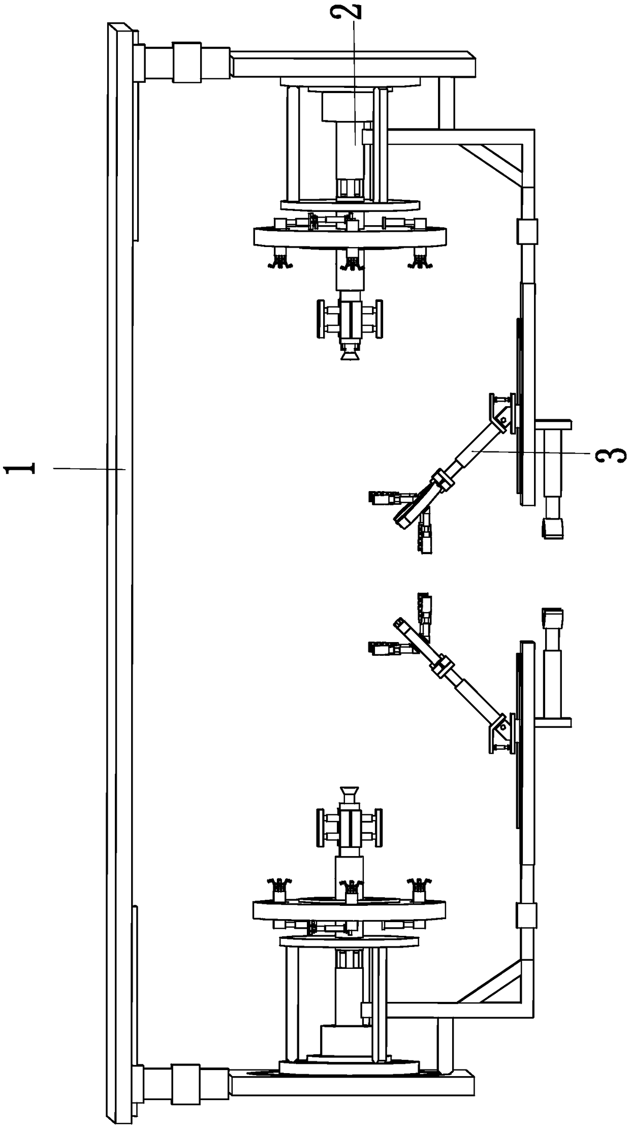
[0035] Such as Figure 1 to Figure 7 As shown, a municipal pipeline installation hoist includes a supporting top plate 1, a positioning cleaning device 2 and a fixing device 3, and a positioning cleaning device 2 is installed on the left and right ends of the bottom of the supporting top plate 1, and each positioning cleaning device A fixing device 3 is installed on each device 2 .

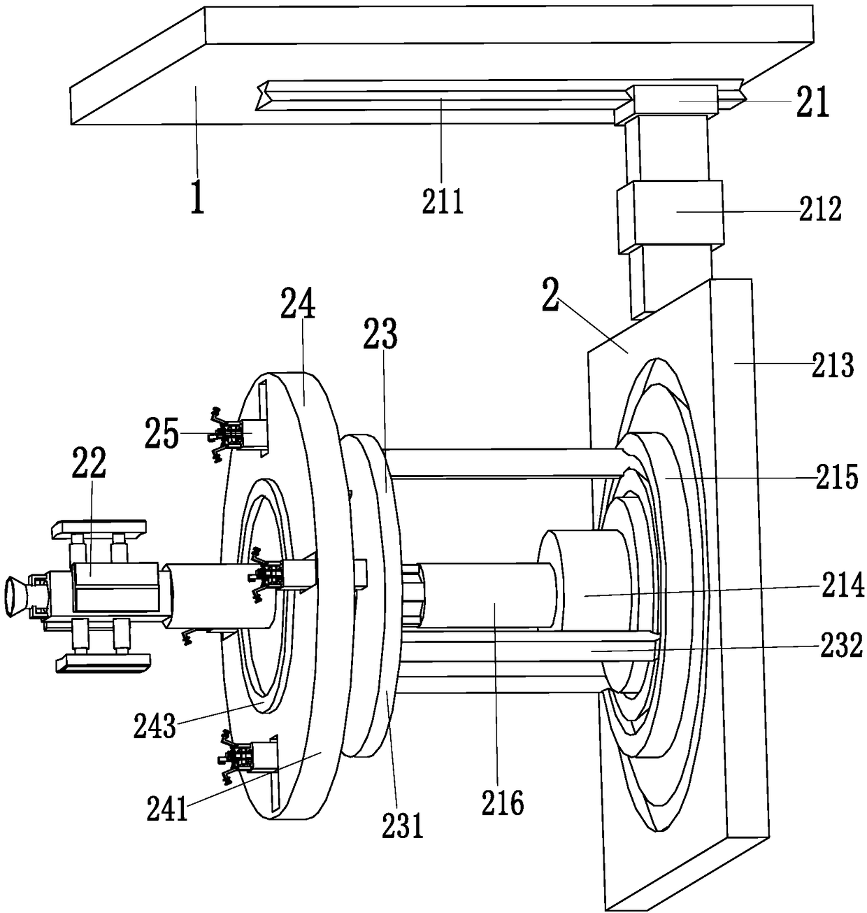
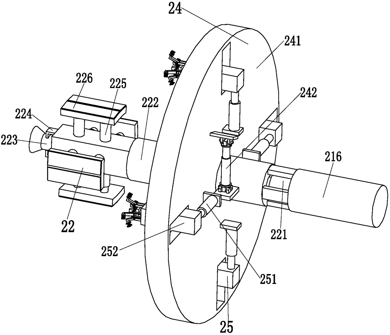
[0036] The positioning cleaning device 2 includes a positioning adjustment mechanism 21, a positioning cleaning mechanism 22, a stable branch chain 23, a locking mechanism 24 and four clamping mechanism...


PUM


Abstract

The invention relates to a municipal pipeline installation lifting machine. The municipal pipeline installation lifting machine includes a support top plate, two location cleaning devices and fixing devices; the location cleaning devices are mounted at the left and right ends of the bottom of the support top plate respectively, and one fixing device is mounted on each location cleaning device; each location cleaning device includes a location adjusting mechanism, a location cleaning mechanism, a stable branch chain, a block-out mechanism and four clamp mechanisms. By the adoption of the municipal pipeline installation lifting machine, the difficulties can be overcome that according to current T-shaped pipe lifting, the labor intensity is high, human assistance is needed to fix T-shaped pipes, the interiors of the T-shaped pipes cannot be automatically cleaned, the effect of manually cleaning the T-shaped pipes is poor, the T-shaped pipes cannot be fixed regarding the structures of theT-shaped pipes, the T-shaped pipes of different types need different lifting appliances, the T-shaped pipes can waggle when lifted, and the T-shaped pipes cannot automatically rotate to suitable installation angles.

Description

technical field [0001] The invention relates to the technical field of municipal pipeline installation, in particular to a hoist for municipal pipeline installation. Background technique [0002] T-shaped pipe is a three-way pipe, which is used to change the direction of fluid. It can be used in water pipelines, oil pipelines and various liquid chemical material transmission pipelines. T-shaped pipes are divided into horizontal pipes and longitudinal pipes. The pipe has two flange connections, and the longitudinal pipe of the T-shaped pipe has a flange connection. The T-shaped pipe is connected to the original pipeline through the flange. Due to the needs of different occasions, the diameter of the T-shaped pipe is the The length is not the same, and the difficulty of lifting the T-shaped tube will increase when the model of the T-shaped tube is too large. [0003] The existing lifting of the T-shaped pipe is mainly carried out in a semi-mechanized manner. First, the T-shap...

Claims


Application Information

Patent Timeline
Patent Type & Authority Applications(China)
IPC IPC(8): B66C1/10B66C1/56B66C13/06B66C13/08B08B9/032
CPCB66C1/10B08B9/0321B66C1/56B66C13/06B66C13/08
Inventor 潘岳燕
Owner 潘岳燕
Why Eureka
Try Eureka