A double circulation anaerobic reactor

An anaerobic reactor and reactor technology, applied in the direction of anaerobic digestion treatment, etc., can solve the problems of low utilization rate of biogas sludge taken out of shutdown, etc., and achieve the effect of increasing the contact area, improving the effect of stirring, and convenient use

Active Publication Date: 2021-02-12
SICHUAN STONG EURO & AMERICA ENVIRONMENT ENG
View PDF9 Cites 1 Cited by
  • Summary
  • Abstract
  • Description
  • Claims
  • Application Information

AI Technical Summary

Problems solved by technology

[0008] In order to solve the above-mentioned problem that the anaerobic reactor needs to be shut down frequently to take out biogas and the problem of low utilization rate of sludge, a double-circulation anaerobic reactor is provided

Method used


Image

  • A double circulation anaerobic reactor
  • A double circulation anaerobic reactor

Examples


Embodiment 1

[0040] As a basic example:

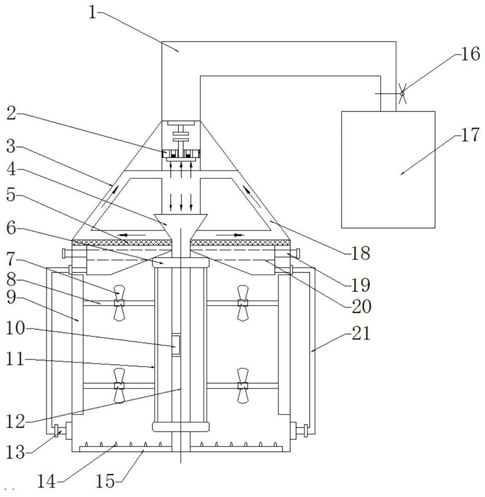
[0041] A double circulation anaerobic reactor, comprising a reactor tank 3, the bottom of the side wall of the reactor tank 3 is connected with a sludge return port 13, it is characterized in that, the reactor tank 3 is installed There is a biogas guide pipe 12 in the vertical direction, the bottom of the biogas guide pipe 12 is connected with a gas distributor 15, and the top of the biogas guide pipe 12 is provided with a gas permeable membrane 5 that separates the reactor tank 3 from top to bottom, which is breathable. A three-phase separator 20 is connected below the membrane 5, and the top of the three-phase separator 20 is open, and the gas-permeable membrane 5 covers the top of the three-phase separator 20 so that the three-phase separator 20 forms a closed structure, and the three-phase separator The bottom of the side of the device 20 is connected with a sludge return pipe 21 protruding outside the reactor tank 3, the lower end of the sludg...

Embodiment 2

[0045] This embodiment focuses on the improvements compared with the above-mentioned embodiments, and the similarities will not be repeated. In this embodiment, the biogas outlet at the top of the reactor tank 3 is connected with a gas outlet pipe 1, and the gas outlet pipe 1 is connected with a biogas storage tank 17, and a storage tank valve 16 is installed on the outlet pipe 1. The gas outlet pipe 1 and the biogas storage tank 17 of this embodiment can directly collect excess overflowing biogas, which facilitates subsequent biogas utilization in one step, makes the whole processing process simpler and faster, and improves work efficiency.

Embodiment 3

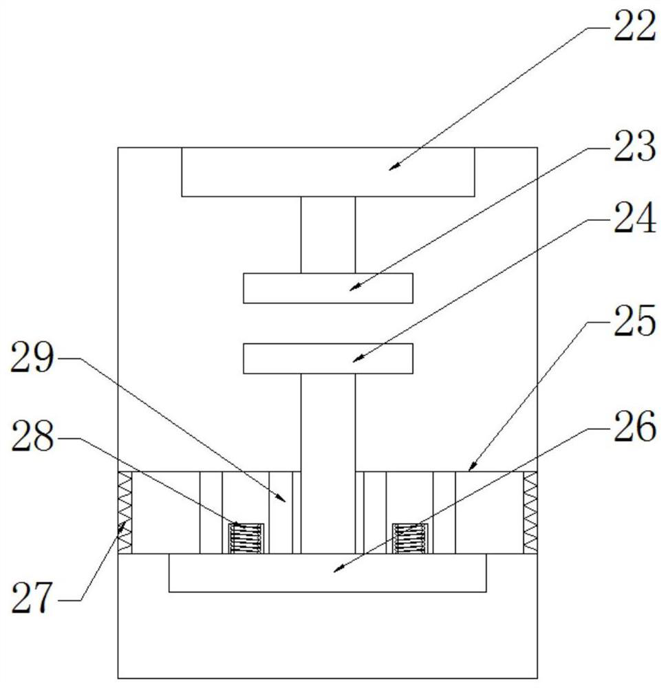
[0047] This embodiment focuses on the improvements compared with the above embodiments, and the similarities will not be repeated. In this embodiment, the side of the piston 25 is connected with a sealing ring 27 . The piston 25 of this embodiment is connected with a sealing ring 27, which can ensure that the piston 25 does not leak gas while moving, thereby ensuring that the gas outlet valve 2 can always realize the function of opening and closing in time, and avoiding the danger of biogas leakage.


PUM


Abstract

The invention discloses a double-cycle anaerobic reactor, which belongs to the technical field of sewage treatment equipment and solves the problems that the anaerobic reactor needs to be shut down frequently to take out biogas and the utilization rate of sludge is not high. The invention includes a reactor tank, A biogas duct is installed in the reactor tank, the bottom of the biogas duct is connected to a gas distributor, the top of the biogas duct is surrounded by a gas-permeable membrane, the bottom of the gas-permeable membrane is connected to a three-phase separator, and the bottom of the side of the three-phase separator is connected to There is a sludge return pipe protruding from the outside of the reactor tank, the lower end of the sludge return pipe is connected to the bottom of the reactor tank, the biogas diversion pipe is connected to a rotating disc, the rotating disc is connected to a sludge scraper, and the bottom of the biogas diversion pipe A vibrating motor is also connected to the inner wall, and an air outlet valve is arranged on the top of the reactor tank. The invention realizes the self-circulation of biogas and the up-and-down circulation of sludge, so that the contact area of ​​waste water is larger and the reaction effect is better.

Description

technical field [0001] The invention belongs to the technical field of sewage treatment equipment, and in particular relates to a double-cycle anaerobic reactor. Background technique [0002] With the development of science and the continuous deepening of scientific research, many new technologies, new materials, and new concepts are widely used in the environmental protection industry, which has made great progress in my country's environmental protection technology. [0003] Anaerobic reactor is a kind of sewage treatment equipment. Its principle is a method of using anaerobic microorganisms to treat sewage. By cultivating microorganisms in sludge, most of the organic pollutants in sewage are degraded into methane by anaerobic fermentation. and carbon dioxide, anaerobic reactors can treat high-concentration organic wastewater in food, biology, chemical and other industries. The essence of the anaerobic process is a series of complex biochemical reactions. Microorganisms i...

Claims


Application Information

Patent Timeline
Patent Type & Authority Patents(China)
IPC IPC(8): C02F3/28
CPCC02F3/28
Inventor 李华
Owner SICHUAN STONG EURO & AMERICA ENVIRONMENT ENG
Why Eureka
Try Eureka