Gas flow control device, method and system

A technology for controlling device and gas flow, which is applied in the direction of valve device, valve operation/release device, heating fuel, etc. It can solve problems such as difficult gas flow automatic control, difficult gas flow multi-level control, etc., and achieve sealing effect Reliable, wear-reducing, wear-reducing effect

Pending Publication Date: 2018-08-28
XINYANG NORMAL UNIVERSITY
View PDF0 Cites 6 Cited by
  • Summary
  • Abstract
  • Description
  • Claims
  • Application Information

AI Technical Summary

Problems solved by technology

[0002] Conventional household appliances are easy to realize automatic control, but due to the particularity of gas, it is difficult to realize automatic control of gas flow, especially it is difficult to realize multi-level control of gas flow

Method used


Image

  • Gas flow control device, method and system
  • Gas flow control device, method and system
  • Gas flow control device, method and system

Examples


Embodiment Construction

[0023] The technical solution of the present invention will be further introduced below in conjunction with specific implementation methods and accompanying drawings.

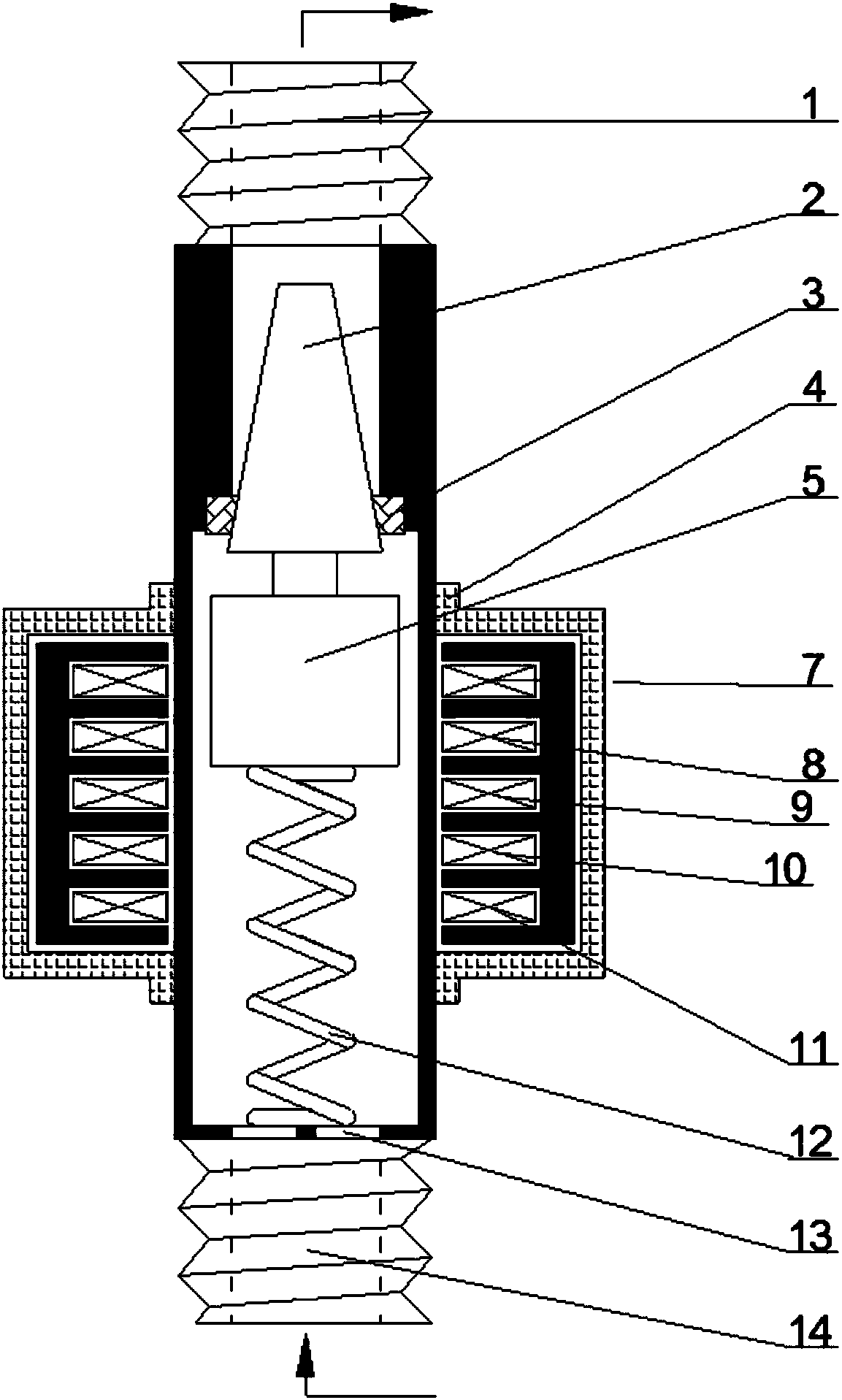
[0024] This specific embodiment discloses a gas flow control device, such as figure 1 As shown, it includes an air inlet passage 14, an air outlet passage 1 and a tapered plug 2 for blocking the entrance of the air outlet passage 1. The plug 2 includes a head with a small cross-sectional area and a large bottom with a cross-sectional area. figure 1 The middle arrow indicates the gas flow direction. The head of the plug 2 is used to plug the air outlet channel 1, and the end of the air outlet channel 1 is also provided with a rubber ring 3, so that the sealing effect is better when the plug 2 plugs the air outlet channel 1. The bottom of the plug 2 is connected with the armature 5, and the outlet end of the air inlet channel 14 is provided with a spring bracket 13, and the armature 5 and the spring bracket 13 a...


PUM


Abstract

The invention discloses a gas flow control device which comprises a gas inlet channel, a gas outlet channel and a plug for sealing an inlet of the gas outlet channel. The plug is connected with an armature; the armature is connected with the gas inlet channel through a spring; a coil group is arranged on the periphery of the armature; when the coil group is electrified, the plug can be applied with forces with different magnitudes through the armature; and when the coil group is not electrified, all armature or part of the armature is located in the encirclement of the coil group. The invention further discloses a control method of the device, and a system adopting the device. According to the gas flow control device, the control method of the device, and the system adopting the device provided by the invention, different groups of coils in the coil group are electrified so as to apply the forces with different magnitudes to the plug, so that multi-grade control of a gas flow is realized. When the coil group stops being electrified, a sealing effect of the plug can be more reliable through the superposition of an elastic force of the spring and a gas pressure. When the plug is opened, except for the gas outlet channel, no gap exists for the gas to contact the outside, so that the gas can be prevented from leaking, and the device has a better anti-leakage function compared witha traditional electromagnetic valve.

Description

technical field [0001] The invention relates to the field of gas cookers, in particular to a gas flow control device, method and system. Background technique [0002] Conventional household appliances are easy to realize automatic control, but due to the particularity of gas, it is difficult to realize automatic control of gas flow, especially it is difficult to realize multi-level control of gas flow. Contents of the invention [0003] Purpose of the invention: The purpose of the present invention is to provide a gas flow control device and method capable of realizing multi-level control of gas flow, and a closed-loop system capable of realizing automatic control of gas flow. [0004] Technical solution: The gas flow control device according to the present invention includes an air inlet channel, an air outlet channel, and a plug for blocking the inlet of the air outlet channel. The plug is connected to an armature, and the armature is connected to the air inlet channel t...

Claims


Application Information

Patent Timeline
Patent Type & Authority Applications(China)
IPC IPC(8): F16K1/00F16K31/06F16K37/00F24C3/10F24C3/12H01F7/16
CPCF16K1/00F16K31/0655F16K31/0679F16K37/0025F24C3/103F24C3/126H01F7/16
Inventor 余大庆马建忠孙柱柱赵骄阳程龙陆翔宇马森
Owner XINYANG NORMAL UNIVERSITY
Why Eureka
Try Eureka