
Multifunctional flexible grounding device

A flexible grounding and multi-functional technology, applied in circuit devices, emergency protection circuit devices, emergency protection circuit devices for limiting overcurrent/overvoltage, etc. , burning and other problems to achieve the effect of ensuring accuracy

Active Publication Date: 2018-08-28
HUAZHONG UNIV OF SCI & TECH
View PDF6 Cites 16 Cited by
  • Summary
  • Abstract
  • Description
  • Claims
  • Application Information

AI Technical Summary

Problems solved by technology

Small resistance grounding can accurately and quickly cut off the fault line, the overvoltage level is low, but its power supply reliability is low, and the line tripping rate is high
In particular, the current grounding resistors are all linear resistors with constant resistance. When non-metallic ground faults or intermittent ground faults occur in the distribution network, the fault current is generally in the range of tens to hundreds of amperes. When the action value of zero-sequence overcurrent protection is reached, the faulty line will not be cut off, and the grounding resistor will accumulate a lot of heat due to the long-term flow of small current, and may eventually burn out due to the long-term accumulated heat
[0006] In general, with the complexity of the power system structure and operation mode, the requirements for the grounding method of the distribution network may change, and the shortcomings of the above two grounding methods have not been well resolved.

Method used


Image

  • Multifunctional flexible grounding device
  • Multifunctional flexible grounding device
  • Multifunctional flexible grounding device

Examples


Embodiment Construction

[0041] In order to make the object, technical solution and advantages of the present invention clearer, the present invention will be further described in detail below in conjunction with the accompanying drawings and embodiments. It should be understood that the specific embodiments described here are only used to explain the present invention, not to limit the present invention. In addition, the technical features involved in the various embodiments of the present invention described below can be combined with each other as long as they do not constitute a conflict with each other.

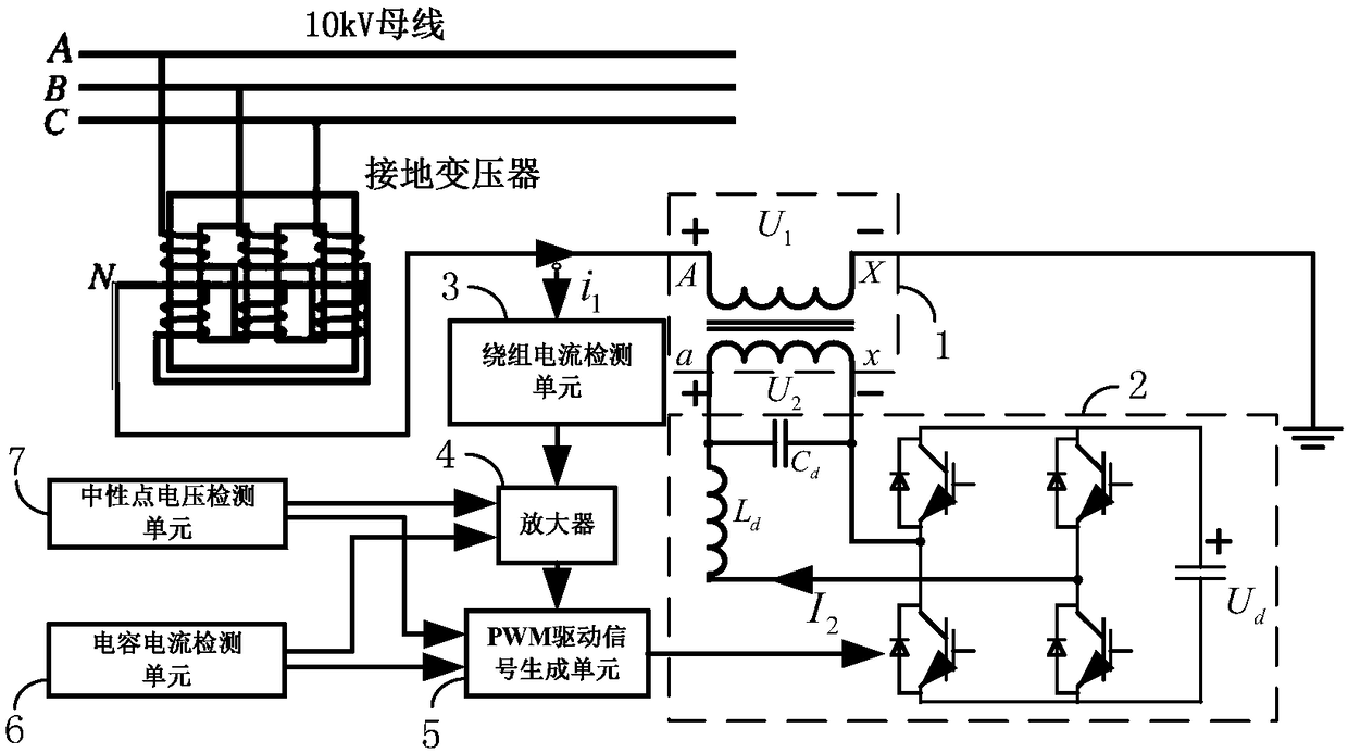
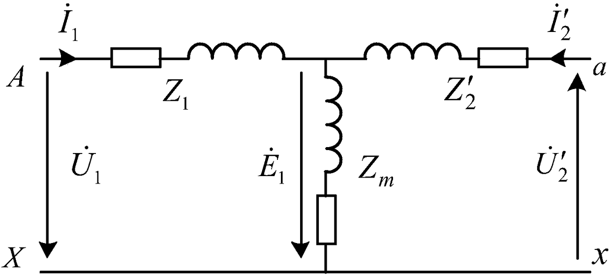
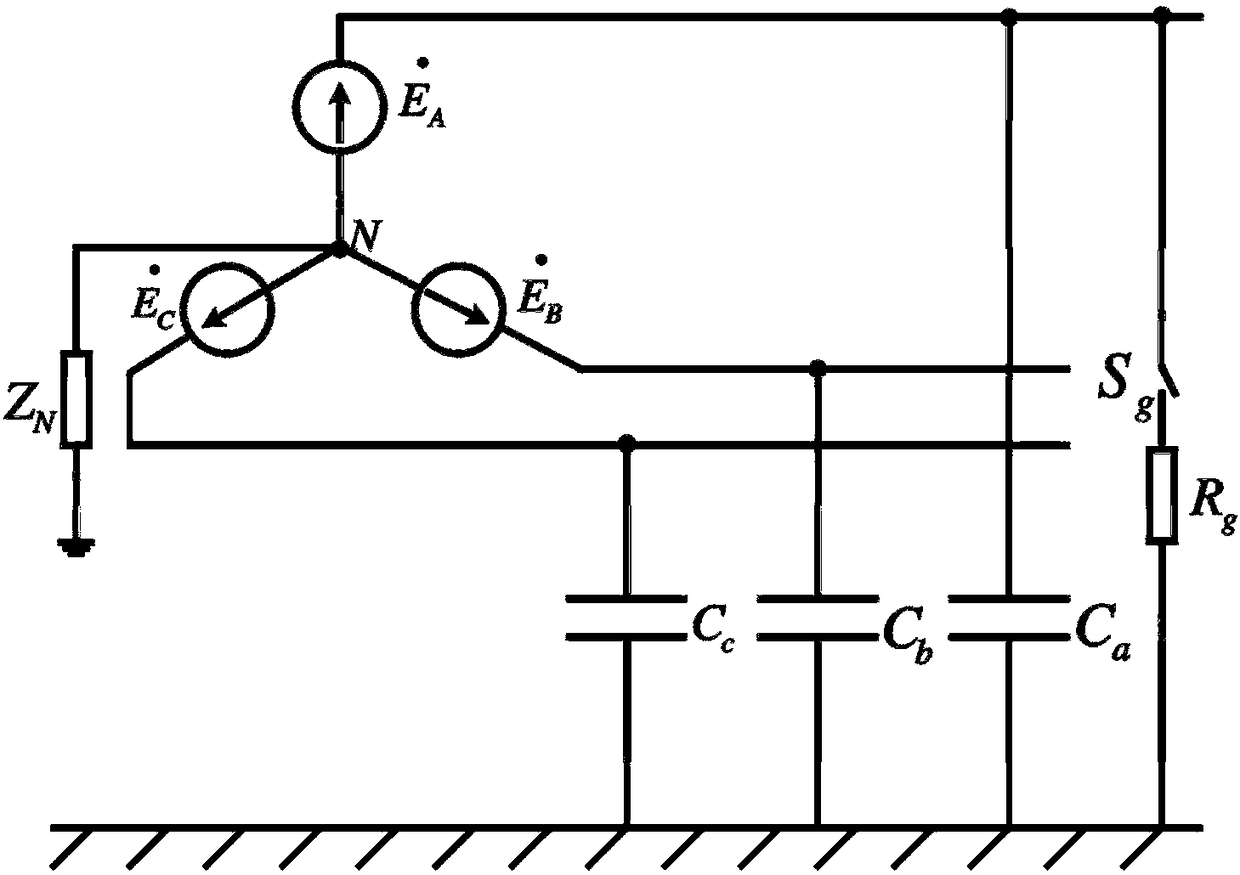
[0042] The multi-functional flexible grounding device proposed by the present invention is aimed at the fact that the current conventional grounding device cannot make real-time adjustments according to changes in the power system structure and operation mode to meet the requirements of the distribution network for the grounding method (that is, the requirements for flexible grounding). In addit...


PUM


Abstract

The invention discloses a multifunctional flexible grounding device, which comprises a transformer, a voltage source inverter, a winding current detection unit, an amplifier, a PWM drive signal generation unit, a capacitance current detection unit and a neutral point voltage detection unit. The winding current detection unit is used for generating a current signal. The amplifier amplifies the current signal to obtain a reference signal. The voltage source inverter is used for generating a current or voltage which is in the same frequency as the reference signal and acts on the secondary side winding of the transformer. The neutral point is grounded through the arc suppression coil, and the capacitance current detection unit is used for detecting the current of the grounding capacitor and calculating the first amplification factor, and the primary side winding of the transformer is equivalent to the continuously adjustable inductance. When the neutral point is grounded through the smallresistor, the neutral point voltage detection unit detects the neutral point voltage and calculates the second amplification factor, and the primary side winding of the transformer is equivalent to acontinuously adjustable small resistor. By means of different control modes, the two neutral point grounding modes can be realized without adjusting devices.

Description

technical field [0001] The invention belongs to the technical field of adjustable reactors, and more specifically relates to a multifunctional flexible grounding device. Background technique [0002] In my country's power system, the distribution network is the part of the entire power system that is closest to the industrial users and civilian users at the end of power distribution. The distribution network plays an extremely important role in the distribution of electric energy. Issues such as power supply reliability, power quality, and economy of the distribution network directly affect various sectors of the national economy and people's daily life. Choosing an appropriate neutral point grounding method is the most direct and effective way to improve the power supply reliability and safe operation level of distribution network. The grounding method of the neutral point of the distribution network is a technical problem that combines many factors, which is related to pe...

Claims


Application Information

Patent Timeline
Patent Type & Authority Applications(China)
IPC IPC(8): H02H9/08H02H9/04
Inventor 李达义林哲侃陈建春胡晶杨凯
Owner HUAZHONG UNIV OF SCI & TECH
Learn More