
SMD (Surface Mounting Device) nut and circuit board assembly

A circuit board assembly and circuit board technology, which is applied in the direction of installation board safety device, support structure installation, clamping/drawing device, etc., can solve the problems of inconvenience for installation personnel, fixed installation specifications, small installation range, etc., and achieve installation and Easy and simple disassembly, firm and stable installation, and a wide range of installation effects

Pending Publication Date: 2018-08-28
XIANNING VOCATIONAL TECHN COLLEGE
View PDF0 Cites 4 Cited by
  • Summary
  • Abstract
  • Description
  • Claims
  • Application Information

AI Technical Summary

Problems solved by technology

[0005] Aiming at the deficiencies of the prior art, the present invention provides a patch nut and a circuit board assembly, which has the advantages of convenient installation, a wide range of installation specifications, can be adapted to install various mounting seats and low manufacturing cost, and solves the problem when installing circuit boards. It is inconvenient to install, the installation procedure is cumbersome, and the installation specifications of the circuit board are fixed, the installation range is small, the existing splicable circuit boards cannot be spliced ​​into various shapes, and it is suitable for some irregular LED lights, and the manufacturing cost is high , increasing production costs and causing inconvenience to installers

Method used


Image

  • SMD (Surface Mounting Device) nut and circuit board assembly
  • SMD (Surface Mounting Device) nut and circuit board assembly
  • SMD (Surface Mounting Device) nut and circuit board assembly

Examples


Embodiment Construction

[0021] The following will clearly and completely describe the technical solutions in the embodiments of the present invention with reference to the accompanying drawings in the embodiments of the present invention. Obviously, the described embodiments are only some, not all, embodiments of the present invention. Based on the embodiments of the present invention, all other embodiments obtained by persons of ordinary skill in the art without making creative efforts belong to the protection scope of the present invention.

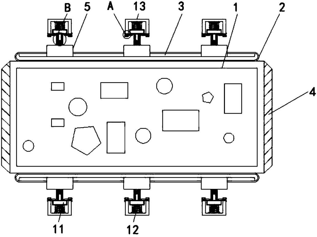
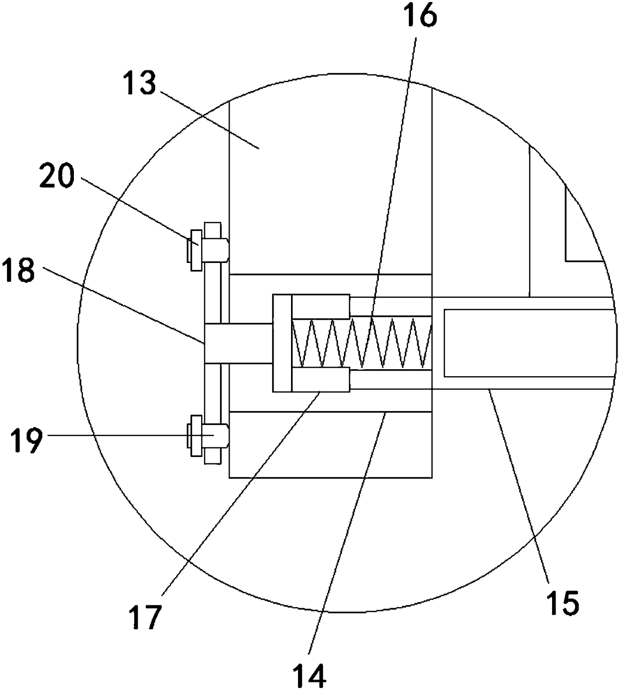
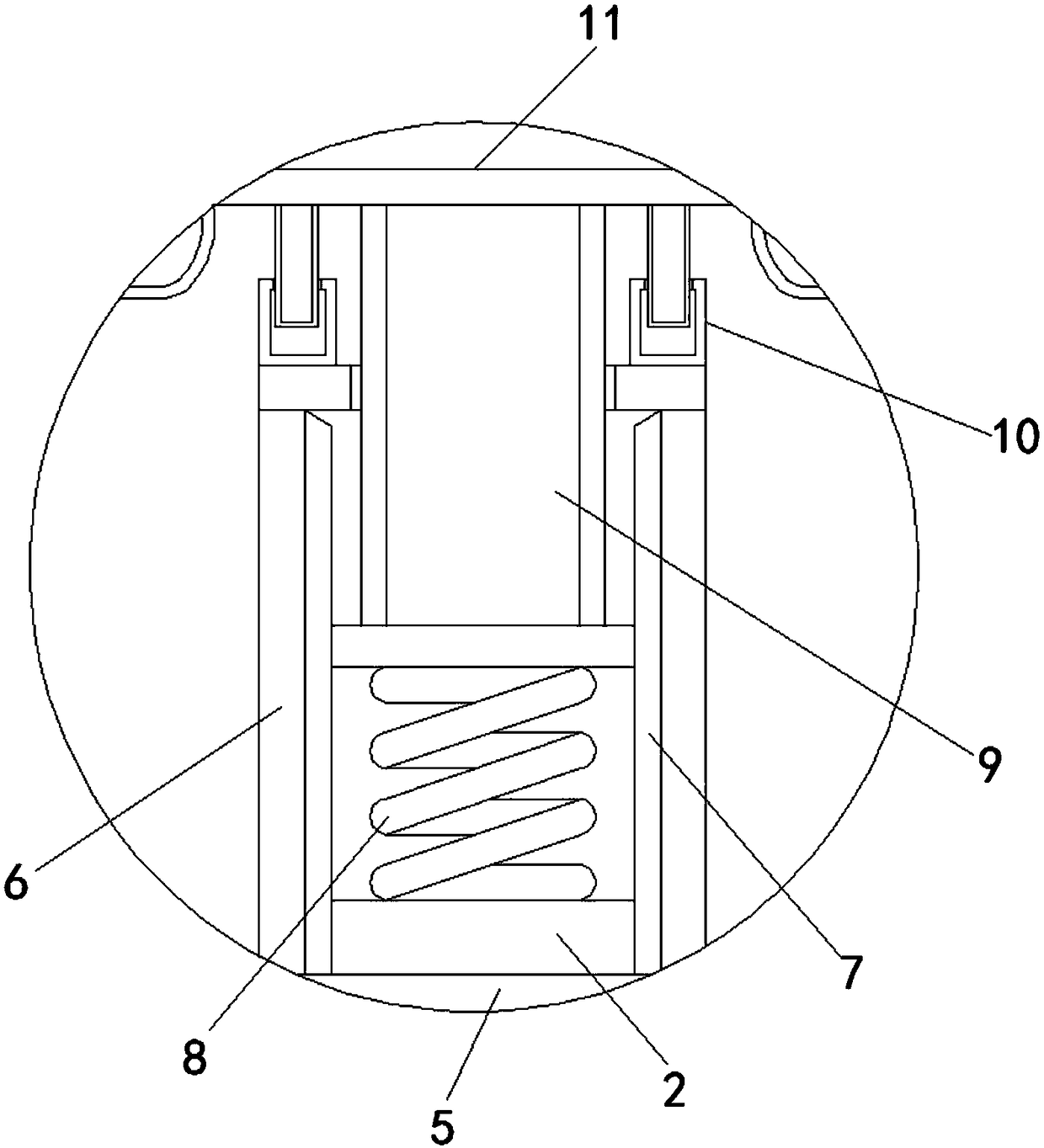
[0022] see Figure 1-3 , a patch nut and a circuit board assembly, including a circuit board 1, a guide rail 2 is fixedly installed on the top and bottom of the circuit board 1, by setting the guide rail 2, the front of the guide rail 2 is provided with a first chute 3, by setting The first chute 3, the slide block 5 can move on the inner wall of the chute 3, so the movable frame 6 can move thereupon, so the position of the clamping plate 11 can be changed by ...


PUM


Abstract

The invention relates to the technical field of power equipment and discloses an SMD (Surface Mounting Device) nut and a circuit board assembly. The circuit board assembly comprises a circuit board, wherein guide rails are fixedly mounted at the top end and the bottom end of the circuit board; first slide grooves are formed in the front sides of the two guide rails; plug boards are fixedly mountedat the left and right sides of the circuit board; slide blocks are movably connected to the front sides of the first slide grooves; movable frames are fixedly mounted at one sides of the slide blocksaway from the circuit board; and second slide grooves are formed in opposite sides of the inner walls of the movable frames. The SMD nut and the circuit board assembly have the advantages that the guide rails are arranged, the first slide grooves are formed in the front sides of the guide rails, the slide blocks can move on the inner walls of the slide grooves by the arrangement of the first slide grooves to enable the movable frames to move, the positions of clamping boards can be changed by moving the slide blocks, and then, the circuit board can be clamped with clamping bases in differentpositions, so that the mounting range of the same circuit board is wider, and the circuit board can be mounted more conveniently by a user.

Description

technical field [0001] The invention relates to the technical field of electric equipment, in particular to a patch nut and a circuit board assembly. Background technique [0002] The names of circuit boards include ceramic circuit boards, alumina ceramic circuit boards, aluminum nitride ceramic circuit boards, circuit boards, PCB boards, aluminum substrates, high-frequency boards, thick copper boards, impedance boards, PCBs, ultra-thin circuit boards, ultra-thin Circuit boards and printed (copper etching technology) circuit boards, etc., circuit boards make circuits miniaturized and intuitive, and play an important role in mass production of fixed circuits and optimizing the layout of electrical appliances. Circuit boards can be called printed circuit boards or printed circuits Board, the English name is PCB and FPC circuit board (FPC circuit board is also called flexible circuit board. Flexible circuit board is a kind of highly reliable, excellent flexible circuit board ma...

Claims


Application Information

Patent Timeline
IPC IPC(8): H05K7/14
CPCH05K7/1407H05K7/1418
Inventor 楚微玮
Owner XIANNING VOCATIONAL TECHN COLLEGE
Learn More