Speed reducer with internal-tooth flexible gear

A technology of reducer and flexible spline, which is applied in the direction of gear transmission, belt/chain/gear, mechanical equipment, etc. It can solve the problems of increasing the cost of deformation bearings, the teeth cannot be completely meshed, and the use conditions are limited, so as to improve the meshing The effect of strength, low machining accuracy, and good output accuracy

Pending Publication Date: 2018-08-31
昆山汉升达传动科技有限公司
View PDF6 Cites 3 Cited by
  • Summary
  • Abstract
  • Description
  • Claims
  • Application Information

AI Technical Summary

Problems solved by technology

[0005] 1. Weak meshing strength: When the internal ring gear with variable tooth shape meshes with the planetary gear, the tooth shape cannot be completely meshed, it is partial contact, and the number of meshing teeth is small, which leads to insufficient meshing strength and a decrease in load-bearing torque;
[0006] 2. Large backlash: Since the internal ring gear with variable tooth shape cannot be completely meshed with the planetary gear, it is easy to produce a large backlash. To improve the backlash, higher machining accuracy is required;
[0007] 3. Larger gear wear: When the variable-toothed inner ring gear meshes with the planetary gear, there will be rolling friction and sliding friction at the same time, causing the gear to wear easily
[0011] 2. The start-up torque is large, and the cost of the deformable bearing must be increased: a deformable bearing needs to be installed between the wave generator and the inner wall of the flexspline to reduce the friction between the wave generator and the inner wall of the flexspline. Therefore, at the moment of starting, It is necessary to deform the deformation bearing and the flexible spline at the same time, resulting in a large starting torque, and the existence of the deformation bearing also increases the cost;
[0012] 3. Poor reversibility: When some reverse input is required at the output end, since the higher starting torque becomes a higher gripping force, a higher reverse input torque is required to operate, which is easy to damage the gear and cause the condition of use restricted

Method used


Image

  • Speed reducer with internal-tooth flexible gear
  • Speed reducer with internal-tooth flexible gear
  • Speed reducer with internal-tooth flexible gear

Examples


Embodiment Construction

[0043] The present invention will be further described below in conjunction with the accompanying drawings and specific embodiments, so that those skilled in the art can better understand the present invention and implement it, but the examples given are not intended to limit the present invention.

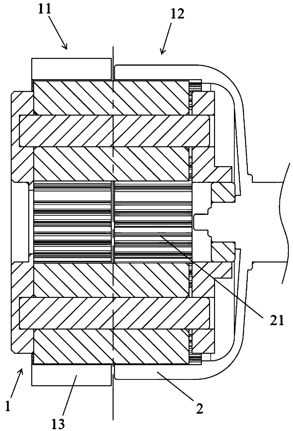
[0044] refer to figure 1 As shown, an embodiment of the internal tooth flexible gear reducer of the present invention has a planetary gear set 1 and a flexible gear 2, and the planetary gear set is provided with a first meshing part 11 and a second meshing part 12, and the first meshing part and the The inner ring gear 13 of the planetary gear set is connected, and the planetary gear set meshes and rotates in the inner ring gear; the internal tooth part 21 is arranged on the inner wall of the flex spline, and the inner gear part is connected with the second meshing part, and the flex spline is on the outer circumference of the planet gear set Mesh rotation; at this time, the first...


PUM


Abstract

The invention discloses a speed reducer with an internal-tooth flexible gear. The speed reducer comprises a planetary gear group, an internal tooth ring, the flexible gear and a housing, wherein a first engagement part and a second engagement part are arranged on the planetary gear group; the internal tooth ring is connected with the first engagement part of the planetary gear group; an internal tooth part is arranged on the inner wall of the flexible gear, and is connected with the second engagement part of the planetary gear group; and an accommodating cavity is formed in the housing, and the planetary gear group, the internal tooth ring and the flexible gear are arranged in the accommodating cavity. The speed reducer disclosed by the invention is high in engagement strength, capable oflowering the accuracy requirements of part machining and achieving high-accuracy output, and low in preparation cost; and moreover, the gear is low in wear and high in reversibility.

Description

technical field [0001] The invention relates to the field of reducers, in particular to an internal tooth flex gear reducer. Background technique [0002] The reducer plays the role of matching speed and transmitting torque between the prime mover and the working machine or the actuator, and is a relatively precise machine. The purpose of using it is to reduce the speed and increase the torque. It has a wide variety, different models, and different types have different uses, among which planetary reducers and harmonic reducers are commonly used types. [0003] The planetary reducer is tightly combined with an inner gear ring on the gearbox housing. There is a sun gear driven by external power in the center of the ring gear. In the gear set, the planetary carrier is provided with an output shaft. When the power drives the sun gear, it can drive the planetary gear to rotate and follow the track of the inner gear ring to revolve along the center. The rotation of the planetary...

Claims


Application Information

Patent Timeline
Patent Type & Authority Applications(China)
IPC IPC(8): F16H1/32F16H57/12
CPCF16H1/32F16H57/12F16H2057/127
Inventor 叶骏绅
Owner 昆山汉升达传动科技有限公司
Why Eureka
Try Eureka