Real simulation method of light environment in room

A simulation method and in-room technology, applied in the field of simulation, can solve the problems of unsatisfactory consumption, low accuracy, and high equipment cost, and achieve fast and accurate measurement, real simulation effect, and fast data collection.

Inactive Publication Date: 2018-08-31
SICHUAN BEE TECH
View PDF0 Cites 2 Cited by
  • Summary
  • Abstract
  • Description
  • Claims
  • Application Information

AI Technical Summary

Problems solved by technology

[0002] The indoor three-dimensional positioning technology in the prior art, when it is applied to model building, usually uses a camera to capture images, and then simulates the construction model through the number of frames of the image. The algorithm is complex, and the equipment used to build the model is expensive and accurate The accuracy is not high, especially for different lighting conditions, the simulation effect of the indoor environment is poor
[0003] When the model established by the method and device in the prior art is displayed on the floor, wallpaper, etc., due to reasons such as light angle and intensity, there is a great difference between the actual construction effect drawing and the displayed picture, which may easily lead to consumption. Dissatisfaction happens

Method used


Image

  • Real simulation method of light environment in room

Examples


Embodiment 1

[0023] A method for realistically simulating the lighting environment in a room, comprising:

[0024] (1) Use the probe pen of the three-dimensional space tracking locator to measure the position information of the wall turning point and the contour points of doors and windows, and use the three-dimensional model building system to realize the preliminary establishment of the three-dimensional model according to the position information;

[0025] Among them, the three-dimensional space tracking locator: use the probe to respectively locate each turning point on the wall, use the probe to respectively locate the contour points of the windows on the wall, and use the probe to respectively locate the contour points of the door on the wall point to locate, record and save each position information; at the same time, use the probe pen to locate the position of the lights in the room respectively, record and save the position information of each light; the specific working process is...

Embodiment 2

[0034] The difference between this embodiment and Embodiment 1 is that in this embodiment, in order to better realize accurate measurement of position information, the probe pen is installed on a telescopic connection bracket.

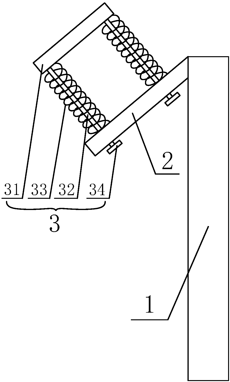
[0035] In order to improve the accuracy of detection, the present invention also provides a mechanical structure of telescopic connection bracket, such as figure 1 As shown, the telescopic connection bracket includes a telescopic rod 1, a fixed rod 2 fixedly connected to the top end of the telescopic rod 1 at one end, a spring holder 3 arranged on the fixed rod 2, and the probe pen is installed on the spring holder 3 superior.

[0036] The spring fixing part 3 includes a fixing ring 31 for fixing the probe pen, one end is fixed with the fixing ring 31, and the other end passes through the guide rod 32 of the fixing rod 2, and the coil spring 33 sleeved on the guide rod 32 is fixed on the guide rod 32. The stop block 34 at the other end of the rod 32. ...


PUM


Abstract

The invention discloses a real simulation method of a light environment in a room. The method comprises the following steps of (1) using the probe of a three-dimensional space tracking positioner to measure the position information of a wall surface turning point and door and window contour points, and the distribution position information of light, and according to the position information, usinga three-dimensional model establishment system to realize the preliminary establishment of a three-dimensional model; (2) using an illumination intensity detection device to detect an illumination intensity F1 at a window position, an illumination intensity F2 at a door position and an illumination intensity F3 at a three-dimensional space tracking positioner position, and through the detected illumination intensities F1, F2 and F3, calculating the corresponding function relation expression of the illumination intensity; and inputting the function relation expression between the illuminationintensity of each light and a distance into the three-dimensional model establishment system, wherein the illumination intensity of one spatial point is the sum of the illumination intensity of the light at the position and the illumination intensity of the natural light of a window position at the position. In the invention, the real simulation of an illumination angle and the intensity in a roomcan be realized.

Description

technical field [0001] The invention belongs to a simulation method, and in particular relates to a method for truly simulating the illumination environment in a room. Background technique [0002] The indoor three-dimensional positioning technology in the prior art, when it is applied to model building, usually uses a camera to capture images, and then simulates the construction model through the number of frames of the image. The algorithm is complex, and the equipment used to build the model is expensive and accurate The accuracy is not high, especially for different lighting conditions, the simulation effect of the indoor environment is poor. [0003] When the model established by the method and device in the prior art is displayed on the floor, wallpaper, etc., due to reasons such as light angle and intensity, there is a great difference between the actual construction effect drawing and the displayed picture, which may easily lead to consumption. Unsatisfactory situat...

Claims


Application Information

Patent Timeline
Patent Type & Authority Applications(China)
IPC IPC(8): G06T17/00G06T15/50G06T19/00
CPCG06T17/00G06T15/506G06T19/003G06T2200/08G06T2210/61G06T2215/16G06T2219/2004
Inventor 周亮全波罗李春梅常彦伟
Owner SICHUAN BEE TECH
Why Eureka
Try Eureka