
Projector sliding door motor control method and control apparatus

A technology for motor control and projector, applied in the direction of motor control, control system, electrical components, etc., can solve problems such as the sliding door cannot be opened or closed normally, and the running resistance of the sliding door increases.

Active Publication Date: 2018-08-31
CHENGDU XGIMI TECH CO LTD
View PDF27 Cites 2 Cited by
  • Summary
  • Abstract
  • Description
  • Claims
  • Application Information

AI Technical Summary

Problems solved by technology

[0003] In the existing projection equipment with an electric sliding door, the sliding door motor usually uses a fixed pull-out torque to drive the opening and closing of the sliding door. Due to the changes in the characteristics of the sliding door track lubricating oil under different temperature conditions, the sliding door will be damaged. The running resistance increases sharply, so that the pull-out torque of the motor is less than the resistance of the sliding door, resulting in the failure of the sliding door to open or close normally

Method used


Image

  • Projector sliding door motor control method and control apparatus
  • Projector sliding door motor control method and control apparatus
  • Projector sliding door motor control method and control apparatus

Examples


Embodiment 1

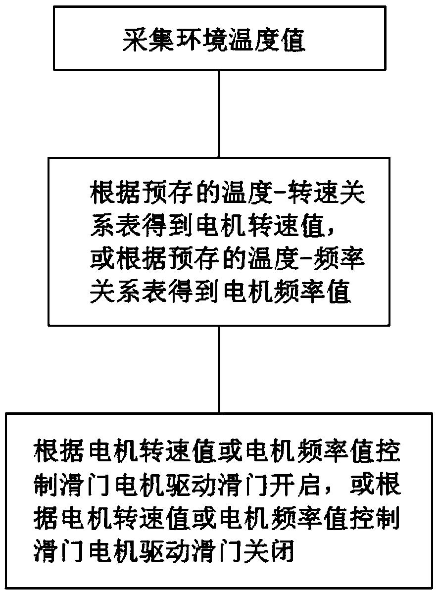
[0034] Such as figure 1 As shown, this embodiment provides a method for controlling a projector sliding door motor, including:

[0035] Step S1: collecting ambient temperature values;

[0036] Step S2: Obtain the motor speed value according to the pre-stored temperature-speed relationship table, or obtain the motor frequency value according to the pre-stored temperature-frequency relationship table;

[0037] Step S3: Control the sliding door motor to drive the sliding door to open according to the motor speed value or the motor frequency value, or control the sliding door motor to drive the sliding door to close according to the motor speed value or the motor frequency value.

[0038] It should be noted here that the temperature-speed relationship table and / or temperature-frequency relationship table is generated before step S1, and then pre-stored in the controller. When implementing this embodiment, only the temperature-speed table can be pre-stored relationship table, or ...

Embodiment 2

[0058] Such as figure 2 As shown, this embodiment provides a projector sliding door motor control device, and the control method provided in Embodiment 1 can be used to control the projector sliding door motor, including

[0059] Data acquisition module: used to collect ambient temperature values;

[0060] Data storage module: used for pre-storing temperature-rotational speed relationship table and / or temperature-frequency relationship table;

[0061] Data generation module: used to generate corresponding motor speed or motor frequency according to the data collected by the data acquisition module and the relationship table stored in the data storage module;

[0062] Motor drive module: used to control the sliding door motor to drive the sliding door to open or close according to the motor speed or motor frequency generated by the data generating module.


PUM


Abstract

The invention discloses a projector sliding door motor control method. The control method comprises the steps of collecting an environment temperature value; obtaining a motor rotary speed value according to a pre-stored temperature-rotary speed relation table, or obtaining a motor frequency value according to a pre-stored temperature-frequency relation table; and controlling a sliding door motorto drive a sliding door to be opened according to the motor rotary speed value or the motor frequency value, or controlling the sliding door motor to drive the sliding door to be closed according to the motor rotary speed value or the motor frequency value. Through the pre-stored temperature-rotary speed relation table or the pre-stored temperature-frequency relation table, the sliding door motorcan be dynamically controlled according to different temperatures, so that it is ensured that the projector electric sliding door can be opened or closed as normal at different temperatures.

Description

technical field [0001] The invention relates to the field of projector sliding door control, in particular to a projector sliding door motor control method and control device. Background technique [0002] A projector, also known as a projector, is a device that can project images or videos onto a screen. It can be connected to a computer, DV, etc. through different interfaces to play the corresponding video signal. The projector is currently widely used in homes, offices, Schools and entertainment places, according to different working methods, there are different types of CRT, LCD, DLP and so on. [0003] In the existing projection equipment with an electric sliding door, the sliding door motor usually uses a fixed pull-out torque to drive the opening and closing of the sliding door. Due to the changes in the characteristics of the sliding door track lubricating oil under different temperature conditions, the sliding door will be damaged. The running resistance increases ...

Claims


Application Information

Patent Timeline
Patent Type & Authority Applications(China)
IPC IPC(8): H02P31/00
CPCH02P31/00
Inventor 钟波肖适刘志明符松
Owner CHENGDU XGIMI TECH CO LTD
Learn More