
Electromagnetic attraction forming device and method

An attractive and electromagnetic technology, applied in the field of metal forming manufacturing, can solve the problems of high manufacturing cost, complex coil structure, low service life, etc., and achieve the effect of widening the forming process window and simple forming control requirements.

Pending Publication Date: 2018-09-04
FUZHOU UNIV
View PDF2 Cites 2 Cited by
  • Summary
  • Abstract
  • Description
  • Claims
  • Application Information

AI Technical Summary

Problems solved by technology

[0003] The object of the present invention is to provide an electromagnetic attraction forming device and method, and propose a method of converting traditional electromagnetic forming repulsive force into an attractive method to form metal parts, so that the forming control requirements of the entire device are simple, and the device does not need to be designed around Discharge coil structure can be used to solve the problems caused by coil production in traditional electromagnetic forming, such as complex coil structure, high production cost, and low service life; and because the current applied to the driving plate and the metal forming part can be actively controlled , can form low-conductivity materials, realize active and flexible control of the forming process, and broaden the forming process window

Method used


Image

  • Electromagnetic attraction forming device and method
  • Electromagnetic attraction forming device and method
  • Electromagnetic attraction forming device and method

Examples


Embodiment 1

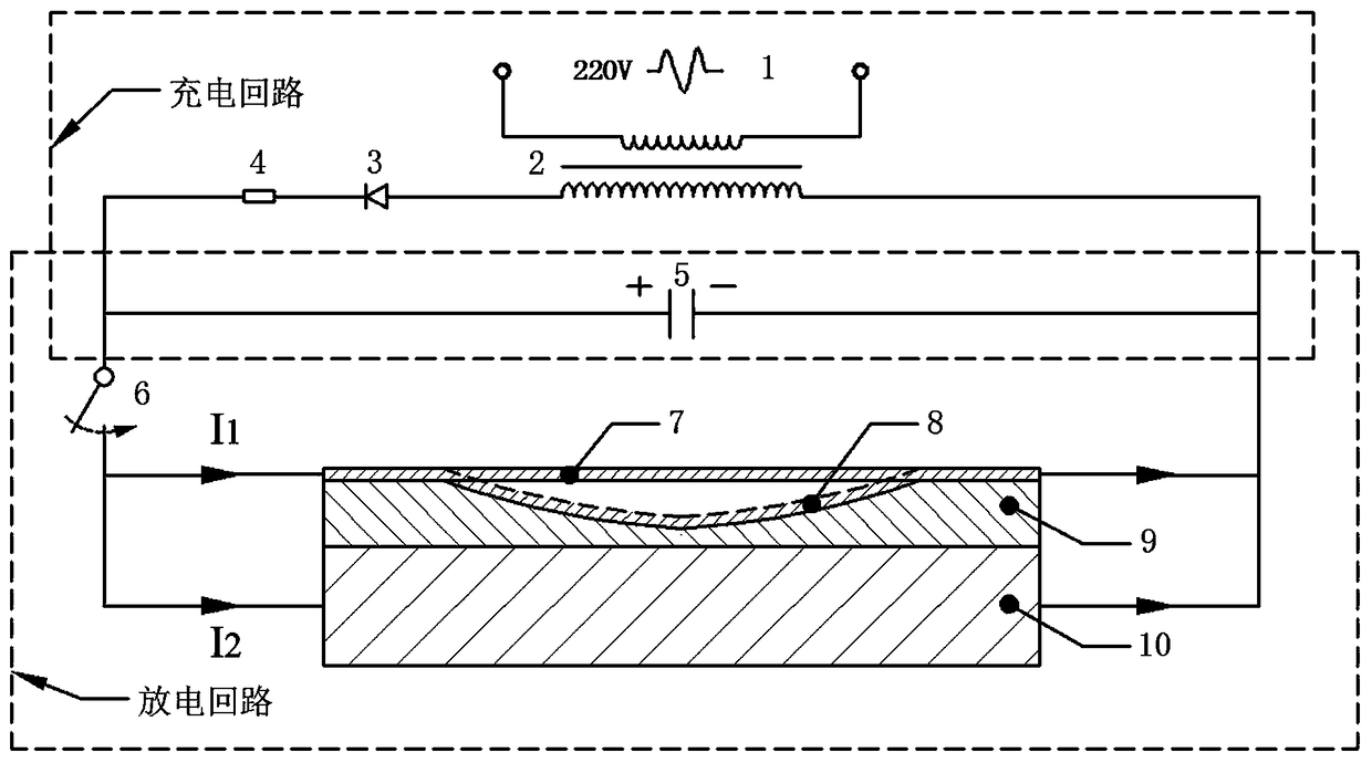
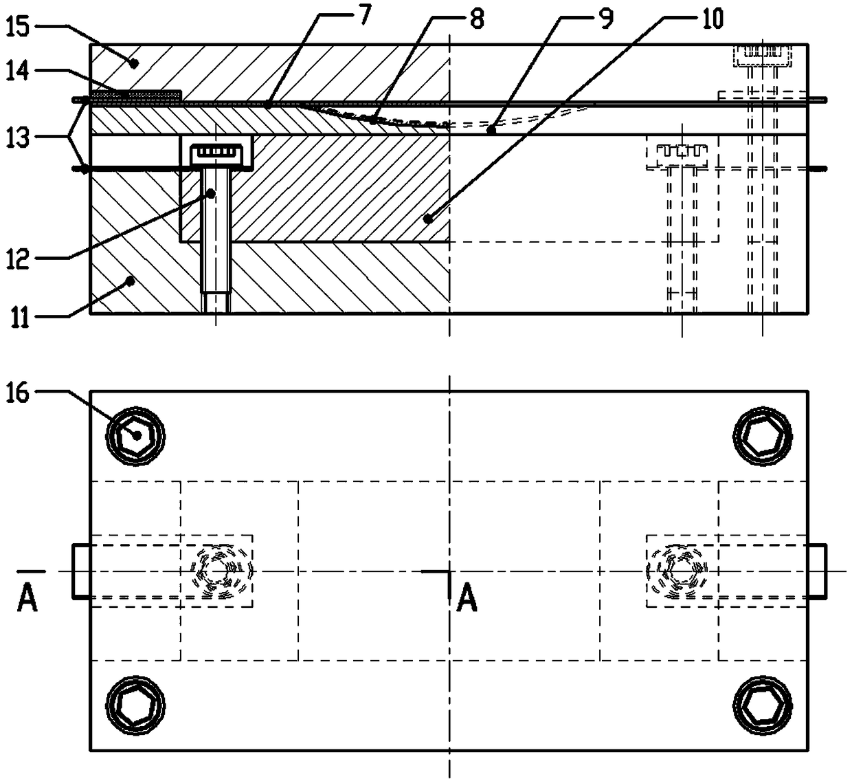
[0033] Please refer to Figure 1 to Figure 2 It is an electromagnetic attraction forming device, including a discharge power supply system, a metal piece to be formed 7, a die 9, a driving plate 10, and positioning and pressing components. The discharge power supply system is respectively connected to the metal part 7 to be formed and the drive plate 10 through wires 13, the die 9 is placed between the metal part 7 to be formed and the drive plate 10, and the side of the die 9 forming the contour of the workpiece is close to the shape of the workpiece to be formed. Formed metal parts 7. The forming device is also equipped with corresponding positioning and pressing components: a base 11 , a pressing plate 12 , a rubber gasket 14 , a wire pressing screw 12 and a pressing plate pressing screw 16 . The base 11 serves as the base of the entire device, and a cavity corresponding to the shape of the driving board 10 is opened in the middle for placing the driving board 10 . The dr...

Embodiment 2

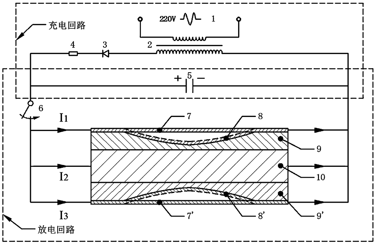
[0046] Refer to as image 3 The electromagnetic attraction forming device shown is different from the device in Embodiment 1 in that a set of second concave molds symmetrical to the concave mold 9 and the metal piece 7 to be formed is set on the side of the drive plate base instead. 9' and the second metal piece 7' to be formed, and apply current to the metal pieces 7 and 7' to be formed on both sides and the driving plate 10 to form two metal plates at the same time.


PUM


Abstract

The invention relates to an electromagnetic attraction forming device and method. The device comprises a discharge power supply system, to-be-formed metal pieces, a driver board and female dies. The discharge power supply system is connected with the to-be-formed metal pieces and the driver board through wires correspondingly. The female dies are arranged between the to-be-formed metal pieces andthe driver board. One sides of the contour shapes of female die formed workpieces are close to the to-be-formed metal pieces. According to the electromagnetic attraction forming device and method, thestructure and control requirements are simple, active control over forming is achieved by directly applying electric current on the driver board and the to-be-formed metal pieces, traditional electromagnetic forming repulsion can be converted into attraction, and no wound discharge coil structure needs to be designed, so that the problems that when coils are manufactured during traditional electromagnetic forming, the coil structure is complex, the manufacturing cost is high, and the service life is short are solved.

Description

technical field [0001] The invention belongs to the technical field of metal forming and manufacturing, and in particular relates to an electromagnetic attraction forming device and method. Background technique [0002] Electromagnetic forming is a method of converting electric energy into magnetic field energy to form metal sheets. The traditional electromagnetic forming process generally uses coils to generate electromagnetic repulsion to the metal sheet for forming. For example, the electromagnetic forming introduced by the Chinese Patent Publication No. CN103817197A The device, when forming, passes current through the coil, and the workpiece is affected by the magnetic field to generate eddy current, and the repulsive force generated between the coil and the workpiece due to the electromagnetic field pushes the workpiece to move to the mold so that the workpiece is close to the mold, so as to form the workpiece. The disadvantage of this electromagnetic forming device usi...

Claims


Application Information

Patent Timeline
IPC IPC(8): B21D26/14
CPCB21D26/14
Inventor 邓将华吕枫黄佳成范治松冯志锋
Owner FUZHOU UNIV
Features
  • Generate Ideas
  • Intellectual Property
  • Life Sciences
  • Materials
  • Tech Scout
  • Unparalleled Data Quality
  • Higher Quality Content
  • 60% Fewer Hallucinations
Learn More