Grabbing, correcting, positioning and shearing mechanism of automatic foot cutter

A foot cutting machine and automatic technology, which is applied in the field of cutting mechanism, correction, positioning and grasping, can solve the problems of low efficiency and inaccurate positioning, and achieve the effect of improving production efficiency, saving manpower and accurate cutting size

Pending Publication Date: 2018-09-04
ZHUHAI FUYUAN ELECTRONICS TECH CO LTD
View PDF0 Cites 3 Cited by
  • Summary
  • Abstract
  • Description
  • Claims
  • Application Information

AI Technical Summary

Problems solved by technology

[0005] The object of the present invention is to provide a grabbing, correcting, positioning, and cutting mechanism of an automatic foot cutting machine, which grabs objects through the air claws arranged at the bottom of the first finger cylinder and the second finger cylinder, and passes through a parallel distance Correction plate, to sort out the deformed pins of the optical coupler, so as to meet the positioning and insertion conditions of the optical coupler pins, the baffle in the cutting mechanism, the shifting and shearing fixing plate and the correction block realize the positioning of the object, and then through the cutter cylinder The cutter at the bottom cuts the objects on the moving and shearing fixed plate, and automatically removes the cut products by the manipulator and puts them into the collection box, and at the same time automatically stores the cut waste to solve the above-mentioned background technology Inaccurate positioning and inefficiency and safety issues of manual work raised in

Method used


Image

  • Grabbing, correcting, positioning and shearing mechanism of automatic foot cutter
  • Grabbing, correcting, positioning and shearing mechanism of automatic foot cutter
  • Grabbing, correcting, positioning and shearing mechanism of automatic foot cutter

Examples


Embodiment 1

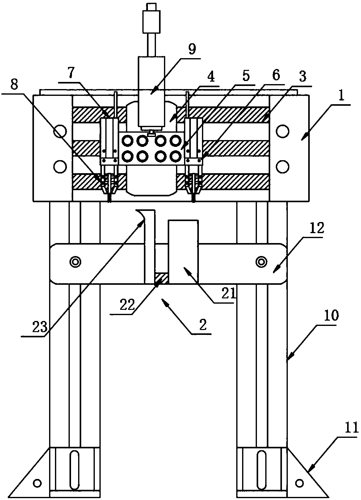
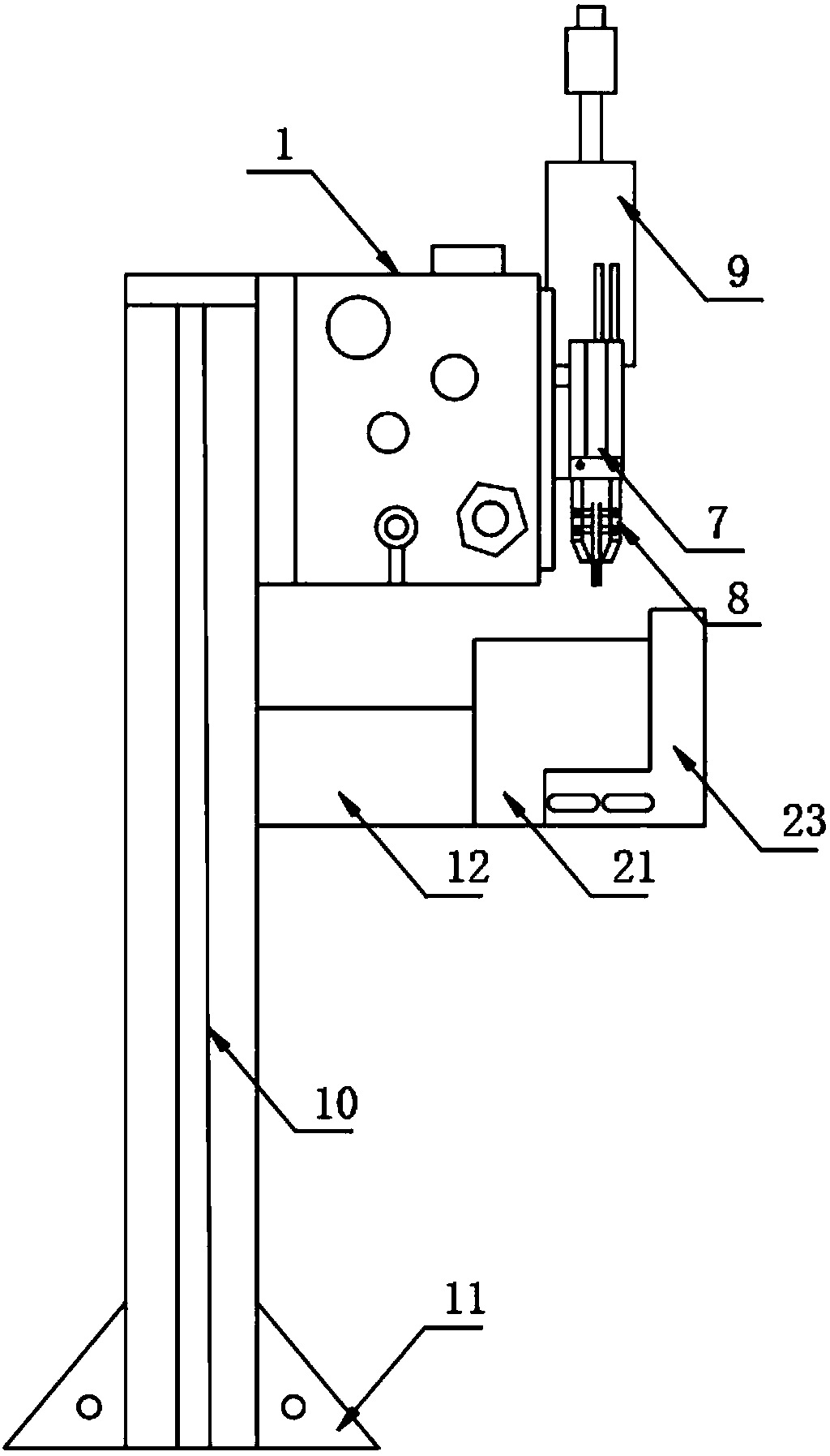
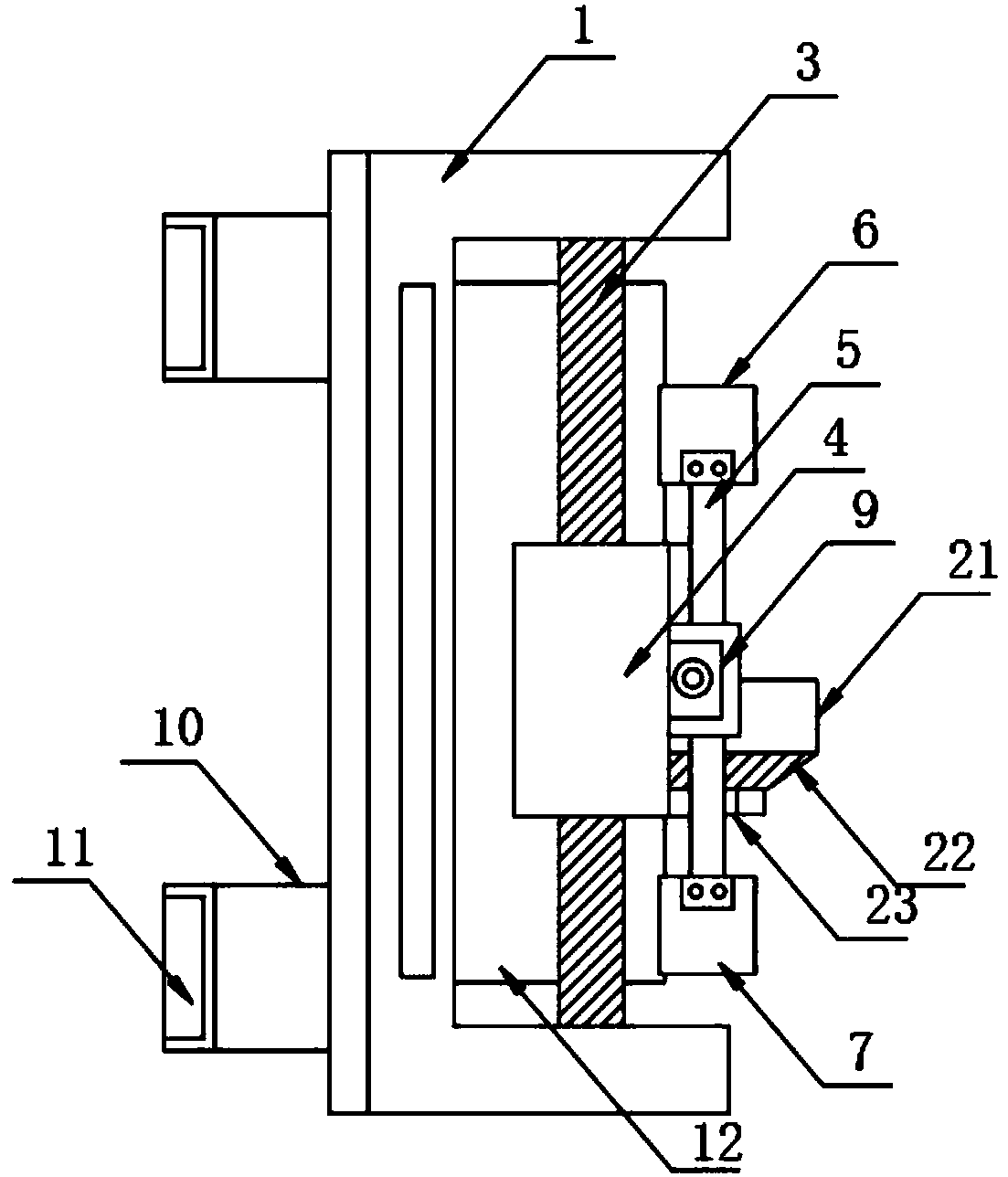
[0024] according to Figure 1-4 The grasping, correcting, positioning, and cutting mechanisms of a kind of automatic foot cutting machine shown include a rodless cylinder 1 and a cutting mechanism 2. The cutting mechanism 2 is arranged at the bottom end of the rodless cylinder 1, and the cutting mechanism 2 A cylinder rod 3 is provided, and a movable connecting plate 4 is arranged on the movable connecting plate 3. One end of the movable connecting plate 4 runs through the side wall of the rodless cylinder 1 and extends to one side of the outer wall of the rodless cylinder 1. The movable connecting plate 4 is movably connected on the rodless cylinder 1, a fixed frame 5 is arranged on one side of the outer wall of the movable connecting plate 4, and a first finger cylinder 6 and a second finger cylinder 6 and a second finger are fixedly arranged at both ends of the fixed frame 5 respectively. Cylinder 7, the bottom of the first finger cylinder 6 and the second finger cylinder 7...

Embodiment 2

[0028] The difference with embodiment 1 is:

[0029] The cutting mechanism 2 includes a baffle plate 21, a moving and cutting fixed plate 22 and a correction block 23, the moving and cutting fixed plate 22 is fixedly arranged on the bottom of one side of the baffle plate 21, and the correction block 23 is fixedly arranged on the moving and cutting shear The other end of the fixed plate 22, and the top of the correction block 23 is higher than the baffle plate 21. Through the correction block 23 in the cutting mechanism 2, the objects placed on the cutting mechanism 2 are corrected and limited, so as to avoid the , the object slides on the 2 cutting mechanism 2, thereby affecting the cutting size of the object;

[0030] One side of the movable connecting plate 4 is fixedly provided with a cutter cylinder 9, and the cutter cylinder 9 is arranged on one side of the top of the fixed frame 5, and the output end of the cutter cylinder 9 is provided with a cutter, which passes throug...

Embodiment 3

[0034] The difference with embodiment 1 and embodiment 2 is:

[0035] The top of the rodless cylinder 1 is provided with a controller, and the first finger cylinder 6, the second finger cylinder 7, the air claw 8 and the cutter cylinder 9 are all electrically connected to an external power supply through the controller, and the external power supply is set For 220V municipal power supply;

[0036] The controller is provided with a start button 12 and an emergency stop button 13 for connecting the external power supply, a rodless cylinder operation button 14 for controlling the operation of the rodless cylinder 1, and a button for controlling the first finger cylinder 6 up and down. The first finger cylinder movement button 15, is provided with the second finger cylinder button 16 that is used to control the second finger cylinder 7 up and down, is provided with the air claw operation button 17 that is used to control the air claw 8 to open and is provided with for controlling ...


PUM


Abstract

The invention discloses a grabbing, correcting, positioning and shearing mechanism of an automatic foot cutter. The mechanism comprises a rodless air cylinder and a shearing mechanism, wherein the shearing mechanism is arranged at the bottom end of the rodless air cylinder, an air cylinder rod is arranged in the shearing mechanism, a movable connecting plate is movably locked to the air cylinder rod, one end of the movable connecting plate penetrates through a side wall of the rodless air cylinder and extends to one side of the outer wall of the rodless air cylinder, the movable connecting plate is movably connected to the rodless air cylinder, a fixed rack is arranged on one side of the outer wall of the movable connecting plate, and a first finger air cylinder and a second finger air cylinder are fixedly arranged at two ends of the fixed rack, separately. By arranging the shearing mechanism, an article on the shearing mechanism is sheared favorably through a slicer under a slicer aircylinder, and the article put on the shearing mechanism is corrected and limited through a connecting block in the shearing mechanism and is prevented from sliding on the shearing mechanism o affectthe shearing dimension of the article when the article is sheared by the slicer.

Description

technical field [0001] The invention relates to the field of grasping, correction, positioning and cutting integrated equipment, in particular to a grasping, correction, positioning and cutting mechanism of an automatic foot cutting machine. Background technique [0002] The optical couple automatic cutting machine uses mechanized mechanisms to grasp, correct, locate and cut objects, collect and count them by category. But existing optical couple cutting foot machine has following weak points: [0003] Inaccurate positioning: The angle of traditional cutting and the order of cutting are incorrect, and the standard consistency of the cut products is poor; [0004] Low efficiency: The traditional method is manual or single cutting, which has low work efficiency and poor safety. Therefore, it is necessary to invent a kind of grasping, correction, location, shearing mechanism of automatic foot cutting machine to solve the above problems. Contents of the invention [0005] T...

Claims


Application Information

Patent Timeline
Patent Type & Authority Applications(China)
IPC IPC(8): B21F11/00B21F23/00
CPCB21F11/00B21F23/00
Inventor 章幼路蔡达伟张宣东
Owner ZHUHAI FUYUAN ELECTRONICS TECH CO LTD
Why Eureka
Try Eureka