
Shear mechanism for cutting spiral coil and then bending countersink head

A technology of helical coil and scissors mechanism, applied in the field of scissors mechanism, can solve the problems of irregularity of metal wires, influence on appearance, irregularity, etc., and achieve the effects of ensuring specification and stability, ingenious and reasonable structure design, and reducing manufacturing cost.

Pending Publication Date: 2018-09-04
宁波市海曙创欣装订设备有限公司
View PDF0 Cites 1 Cited by
  • Summary
  • Abstract
  • Description
  • Claims
  • Application Information

AI Technical Summary

Problems solved by technology

However, the artificially bent metal wire is irregular, affecting the appearance, low work efficiency, and unsafe. The coil binding process must be processed with safety hooks
At present, the only method that can be adopted by various enterprises in this book industry is manual safety hook processing, which leads to low efficiency, irregularity and instability in the production process.

Method used


Image

  • Shear mechanism for cutting spiral coil and then bending countersink head
  • Shear mechanism for cutting spiral coil and then bending countersink head
  • Shear mechanism for cutting spiral coil and then bending countersink head

Examples


Embodiment 1

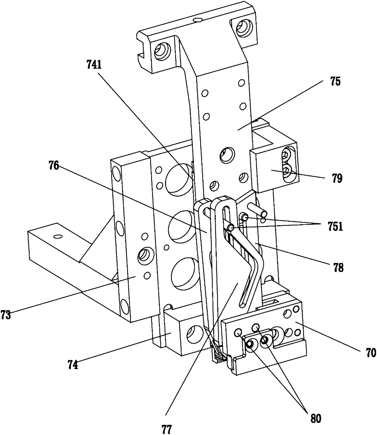
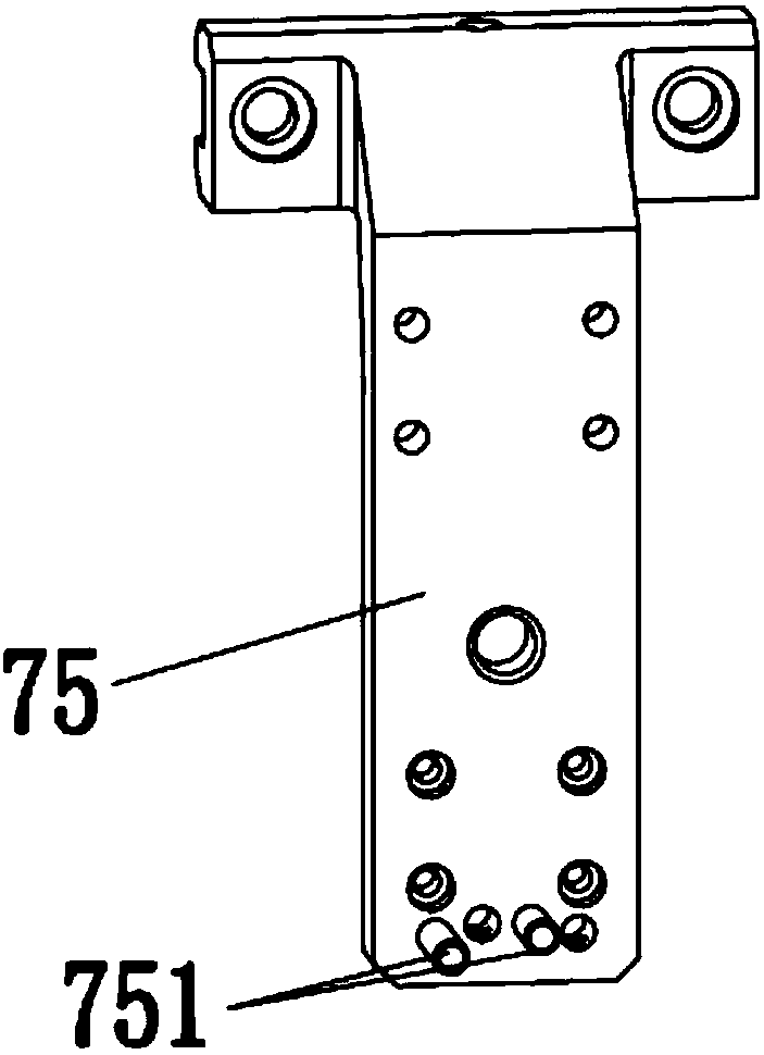
[0033] Such as Figure 1-Figure 7 As shown, the scissors mechanism described in this embodiment to cut the helical coil and bend the hidden head includes an L-shaped fixed plate 74, and a slide rail 741 is fixed on the front side of the transverse part of the L-shaped fixed plate 74, and the L-shaped fixed plate The outside of the longitudinal part of the plate 74 is fixed with a spiral coil positioning frame 70; The side is provided with the alveolus 706 for the corresponding embedded positioning of the spiral coil; the slider of the slide rail 741 is fixed with a connecting arm 75, and the connecting arm 75 is equipped with a shearing knife group that bends the hidden head after cutting the spiral coil; The bottom of the knife set is inserted into the working groove, and after working, the helical coil is cut and the hidden head is bent;

[0034]In the present embodiment, the specific structure of the installation of the shearing knife group is: the shearing knife group inc...


PUM

PropertyMeasurementUnit
angleaaaaaaaaaa
angleaaaaaaaaaa

Abstract

The invention discloses a shear mechanism for cutting a spiral coil and then bending a countersink head. The shear mechanism comprises an L-shaped fixing plate, and is characterized in that a slide rail is fixed to the front side surface of the transversal part of the L-shaped fixing plate, and a spiral coil location frame is fixed to the outer side of the longitudinal part of the L-shaped fixingplate; a working groove is formed in the side of the spiral coil location frame, a through groove allowing the spiral coil to penetrate through is formed in the bottom side of the spiral coil locationframe, and tooth grooves allowing the spiral coil to be correspondingly embedded and located are formed in the two side surfaces of the port of the through groove; a connection arm is fixed to the slide block of the slide rail, and a cutting knife group for cutting the spiral coil and then bending the countersink head is installed on the connection arm; and the bottom of the cutting knife group is inserted into the working groove, and cuts the spiral coil and then bends the countersink head after working. The structure completes the action of cutting, bending and safe hooking-back simultaneously, thereby increasing the working efficiency during production, and improving the safe use performance of the product.

Description

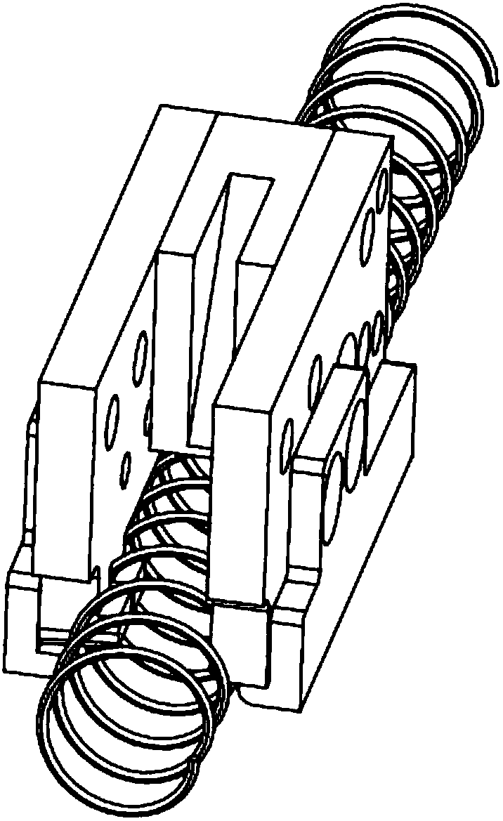
technical field [0001] The invention relates to the technical field of a metal helical coil shearing mechanism in the bookbinding industry, in particular to a scissors mechanism for bending a hidden head after cutting the helical coil. Background technique [0002] At present, in the bookbinding industry, for the bending and hiding process of the spiral (single) coil, what can be done on the equipment is only to manually bend the end of the spiral coil after cutting. However, the artificially bent metal wire is irregular, affecting the appearance, low work efficiency, and unsafe. The coil binding process must be processed with safety hooks. At present, the only method that various enterprises in this book industry can adopt is manual safety hooking, which leads to low efficiency, irregularity and instability in the production process. It is imperative to use mechanical equipment for bending and safety hook processing. Contents of the invention [0003] The purpose of th...

Claims


Application Information

Patent Timeline
Patent Type & Authority Applications(China)
IPC IPC(8): B21F11/00B21F1/00
CPCB21F1/004B21F11/00
Inventor 王伟军叶樟勇
Owner 宁波市海曙创欣装订设备有限公司
Learn More