Special fixture for turning of thin cylindrical parts and operation method thereof

A technology of special fixtures and cylindrical parts, applied in the direction of expanding mandrels, etc., can solve problems such as affecting product quality

Inactive Publication Date: 2018-09-04
FUZHOU UNIV
View PDF8 Cites 4 Cited by
  • Summary
  • Abstract
  • Description
  • Claims
  • Application Information

AI Technical Summary

Problems solved by technology

[0002] At present, when processing thin cylindrical parts, the clamping force of the four-jaw chuck or the bolt-supported fixture acts on several points, forcing the deformation of the tube wall under p

Method used


Image

  • Special fixture for turning of thin cylindrical parts and operation method thereof
  • Special fixture for turning of thin cylindrical parts and operation method thereof
  • Special fixture for turning of thin cylindrical parts and operation method thereof

Examples


Embodiment Construction

[0016] The foregoing descriptions are only preferred embodiments of the present invention, and all equivalent changes and modifications made in accordance with the scope of the patent application of the present invention should fall within the scope of the present invention.

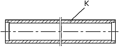
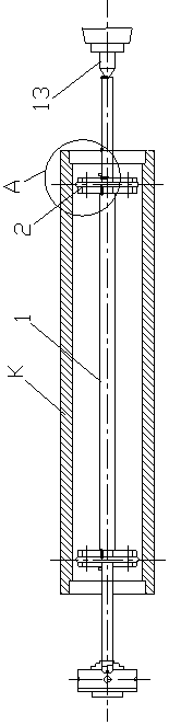
[0017] The special fixture for turning thin cylindrical parts of the present invention includes a mandrel 1 clamped on a three-jaw fixture and an expandable support plate 2 fixedly sleeved on both ends of the mandrel.

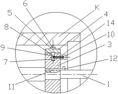
[0018] Further, for reasonable design, the support plate 2 includes an inner disc 3 sleeved on the stepped shaft end of the spindle, and an annular carriage 4 is sleeved on the periphery of the inner disc, and the outer peripheral surface of the annular carriage 4 is provided with The annular groove 5 is sleeved with a wire ring 6 against the inner wall surface of the workpiece, and the inner disc 3 is provided with a plurality of counterbore grooves 7 on the outer peripheral wall surface of th...


PUM


Abstract

The invention relates to a special fixture for turning of thin cylindrical parts and an operation method thereof. The special fixture for turning of the thin cylindrical parts is characterized by comprising a mandrel clamped onto a three-jaw fixture and expandable supporting disks fixedly arranged at the two ends of the mandrel in a sleeving mode; each supporting disk comprises an inner disk arranged at the stepped shaft end of the mandrel in a sleeving mode and an annular drag plate arranged on the periphery of the inner disk in a sleeving mode; the peripheral surface of each annular drag plate is provided with an annular groove, and a steel ring abutting against the inner wall surface of a workpiece is arranged in each annular groove in a sleeving mode; the inner peripheral surface of each inner disk is provided with a plurality of countersink groove; cuphead pins are embedded in the countersink grooves; the sidewall surface of each inner disk is provided with screw holes communicating with the corresponding countersink grooves; fastening screws are arranged in the screw holes; the ends of the fastening screws abut against the inner ends of the cuphead pins, and the outer ends ofthe cuphead pins abut against the inner peripheral wall of the corresponding annular drag plates.

Description

Technical field: [0001] The invention relates to a special clamp for turning processing of thin cylindrical parts and a working method thereof. Background technique: [0002] At present, when processing thin cylindrical parts, the clamping force of the four-jaw chuck or the clamp supported by bolts acts on several points, which forces the pipe wall to deform under pressure. When the pipe is processed and removed from the chuck, It will be found that the outer circle of the compressed pipe wall is polygonal, which seriously affects the quality of the product. Summary of the invention: [0003] The invention provides a special clamp for turning processing of thin cylindrical parts and a working method thereof. The special clamp for turning processing of thin cylindrical parts has a simple structure and reasonable design, which is beneficial to eliminate clamping deformation of the pipe wall. [0004] In order to achieve the above objectives, the present invention adopts the followi...

Claims


Application Information

Patent Timeline
IPC IPC(8): B23B31/40
CPCB23B31/40
Inventor 陈功振
Owner FUZHOU UNIV
Why Eureka
Try Eureka