
Movable connector rapid positioning and clamping tool used for pipelines

A technology for positioning, clamping and joints, applied in workpiece clamping devices, manufacturing tools, etc., can solve the problems of difficult control of clamping force, deformation of joints, low efficiency, etc., to improve clamping quality, reduce labor intensity, The effect of improving positioning accuracy

Inactive Publication Date: 2015-12-02
NANJING RUIFA MACHINERY EQUIP
View PDF5 Cites 3 Cited by
  • Summary
  • Abstract
  • Description
  • Claims
  • Application Information

AI Technical Summary

Problems solved by technology

Due to the unique shape and structure of the joint and the need to carry a large moment load during assembly, the clamping method of the threaded connection between the joint and the pipeline has always been clamped by manual vise, which has the following problems: 1. The labor intensity of the clamping operation Large, low efficiency; 2. The clamping force is not easy to control. If the clamping force is too large, the joint will deform and affect the assembly quality. If the clamping force is too small, the joint cannot be effectively fixed and the assembly operation cannot be completed; 3. The positioning and fastening of the joint The stability of the joint is poor, and the connection between the union and the pipeline can only be done manually, and it is impossible to implement mechanization and automation.

Method used


Image

  • Movable connector rapid positioning and clamping tool used for pipelines
  • Movable connector rapid positioning and clamping tool used for pipelines
  • Movable connector rapid positioning and clamping tool used for pipelines

Examples


Embodiment Construction

[0018] The present invention will be further described below in conjunction with the accompanying drawings and specific embodiments.

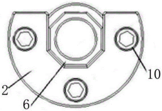
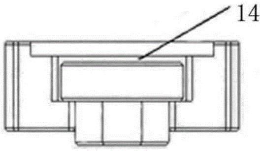
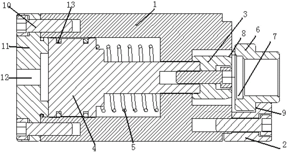
[0019] according to Figure 1-Figure 3 , the clamping body 1 is used to drive or bear the moment load when the joint is assembled, the piston assembly 4 and the return spring 5 in the clamping body 1 drive and position the extension and reset of the clamping head 3, the left end of the clamping body Cover 11 is provided with intake and exhaust holes 12 and air pressure control passages (regulating inflation and deflation, and adjusting high-pressure gas pressure, which is the prior art), and the inner chamber on the back spring side (referring to the side of the back spring) (the inner chamber is located The clamping body) has an air vent connected to the atmosphere, the right side of the clamping body is equipped with a joint 6 and an open chuck 2, and the right cylindrical platform of the clamping body is used for the installation and positio...


PUM


Abstract

The invention relates to the field of positioning and clamping tools, in particular to a movable connector rapid positioning and clamping tool used for pipelines. The movable connector rapid positioning and clamping tool comprises an opening chuck used for clamping a movable connector. The movable connector rapid positioning and clamping tool is characterized by further comprising a clamping body used for positioning the movable connector; the clamping body comprises a movable piston assembly and a movable positioning and clamping head connected with the piston assembly; the positioning and clamping head can extend into a positioning hole of the movable connector so that the rotation central line of the movable connector and the rotation central line of the positioning and clamping head can coincide. The movable connector rapid positioning and clamping tool has the advantages that the labor intensity is lowered during the clamping work of movable connector assembling, the assembling efficiency is improved, the clamping quality of the movable connector is improved, the clamping deformation of the movable connector can be eliminated so that the assembling quality can be improved, the positioning accuracy of the movable connector is improved, and the automatic connection of the movable connector and the pipelines can be achieved through the mechanical device.

Description

technical field [0001] The invention relates to the field of positioning and clamping tooling, in particular to a quick positioning and clamping tooling for a flexible joint for pipelines. Background technique [0002] A large number of metal pipe threads are used to connect pipelines in brakes and living devices on railway vehicles. The characteristics of the car body structure make the pipeline layout complicated and require a large number of unions to connect the pipeline system. Due to the unique shape and structure of the joint and the need to carry a large moment load during assembly, the clamping method of the threaded connection between the joint and the pipeline has always been clamped by manual vise, which has the following problems: 1. The labor intensity of the clamping operation Large, low efficiency; 2. The clamping force is not easy to control. If the clamping force is too large, the joint will deform and affect the assembly quality. If the clamping force is...

Claims


Application Information

Patent Timeline
Patent Type & Authority Applications(China)
IPC IPC(8): B25B11/02
CPCB25B11/02
Inventor 曾九玉
Owner NANJING RUIFA MACHINERY EQUIP
Learn More