Connector plug-in machine of liquid crystal display

A technology for LCD screens and connectors, applied in metal processing, metal processing equipment, manufacturing tools, etc., can solve problems such as decreased vision of workers, damage to power sockets, and increase in defective products, so as to avoid visual damage, reduce labor intensity, and reduce labor intensity. The effect of reducing defective products

Pending Publication Date: 2018-09-04
宁波图锐自动化设备有限公司
View PDF0 Cites 5 Cited by
  • Summary
  • Abstract
  • Description
  • Claims
  • Application Information

AI Technical Summary

Problems solved by technology

[0002] Liquid crystal screens are more and more widely used in electronic products. When using liquid crystal screens, they need to be plugged into power connectors. Generally, the side of the liquid crystal screen connected to power connectors is made of soft materials. In the prior art, due to different The soft material of the LCD screen has different inclination and bending angles, so the process of inserting the energized connector into the energized interface of the LCD screen is generally a manual operation, but manual operation has many disadvantages. When inserting, the operator needs to hold the soft material , and then align the energized connector and insert it into the energized interface. Due to the uncertainty of the operator's operation steps, it is very likely to cause damage to the energized socket to a certain extent, resulting in an increase in defective products. The physical strength and vision requirements of the workers are very high. After working for a long time, the workers' vision will be seriously reduced, which is not conducive to the physical and mental health of the workers. In view of this, we continue to design an LCD screen connector interposer that can replace manual work.

Method used


Image

  • Connector plug-in machine of liquid crystal display
  • Connector plug-in machine of liquid crystal display
  • Connector plug-in machine of liquid crystal display

Examples


Embodiment Construction

[0050] The following are specific embodiments of the present invention and in conjunction with the accompanying drawings, the technical solutions of the present invention are further described, but the present invention is not limited to these embodiments.

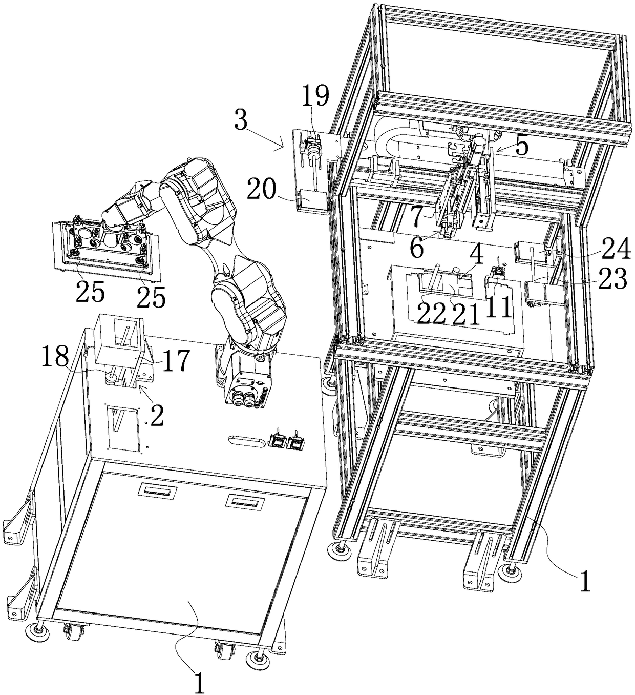
[0051] Such as figure 1 As shown, the LCD screen connector mating machine includes: a fixed frame 1; a liquid crystal screen grasping component, which is arranged on the fixed frame 1, and the liquid crystal screen grasping component is used to grasp and move the liquid crystal screen; The liquid crystal screen positioning component is arranged on the fixed frame 1, and the liquid crystal screen positioning component is used to obtain the position information of the liquid crystal screen and makes the liquid crystal screen grasping component make corresponding adjustments; the connector grasping component is set On the fixed frame 1, the connector grabbing component is used to grab and drive the connector to move; the conn...


PUM


Abstract

The invention belongs to the field of mechanical devices and provides a connector plug-in machine of a liquid crystal display. The machine comprises a fixing frame, a liquid crystal display grabbing assembly, a liquid crystal display positioning assembly, a connector grabbing assembly and a connector positioning assembly, wherein the liquid crystal display grabbing assembly is arranged on the fixing frame and used for grabbing and moving the liquid crystal display; the liquid crystal display positioning assembly is arranged on the fixing frame and used for obtaining position information of theliquid crystal display and enabling the liquid crystal display grabbing assembly to be adjusted correspondingly; the connector grabbing assembly is arranged on the fixing frame and used for grabbinga connector and driving the connector to move; and the connector positioning assembly is arranged on the fixing frame and used for obtaining position information of the connector and enabling the position of the connector grabbing assembly to be adjusted correspondingly. Compared with the prior art, the connector plug-in machine of the liquid crystal display has the advantages that the machine canreplace manpower to enable the electrical connector to be plugged in an electrical interface, damage to the vision of a worker is avoided, and the labor intensity of the worker is relieved.

Description

technical field [0001] The invention belongs to the field of mechanical devices, and in particular relates to a liquid crystal screen connector mating machine. Background technique [0002] Liquid crystal screens are more and more widely used in electronic products. When using liquid crystal screens, they need to be plugged into power connectors. Generally, the side of the liquid crystal screen connected to power connectors is made of soft materials. In the prior art, due to different The soft material of the LCD screen has different inclination and bending angles, so the process of inserting the energized connector into the energized interface of the LCD screen is generally a manual operation, but manual operation has many disadvantages. When inserting, the operator needs to hold the soft material , and then align the energized connector and insert it into the energized interface. Due to the uncertainty of the operator's operation steps, it is very likely to cause damage to...

Claims


Application Information

Patent Timeline
IPC IPC(8): B23P19/02
CPCB23P19/02
Inventor 张明明谭凡高国宾赖俊霖
Owner 宁波图锐自动化设备有限公司
Why Eureka
Try Eureka