Cutting equipment for bills

A technology of cutting equipment and bills, which is applied in metal processing and other directions, can solve problems such as damage to bills, and achieve the effect of avoiding cutting damage

Inactive Publication Date: 2019-12-03
重庆华康印务有限公司
View PDF6 Cites 0 Cited by
  • Summary
  • Abstract
  • Description
  • Claims
  • Application Information

AI Technical Summary

Problems solved by technology

[0004] The present invention intends to provide a cutting device for bills to solve the problem that bills are easily damaged when cutting by the current bill cutting mechanism

Method used


Image

  • Cutting equipment for bills

Examples


Embodiment Construction

[0018] Further detailed explanation through specific implementation mode below:

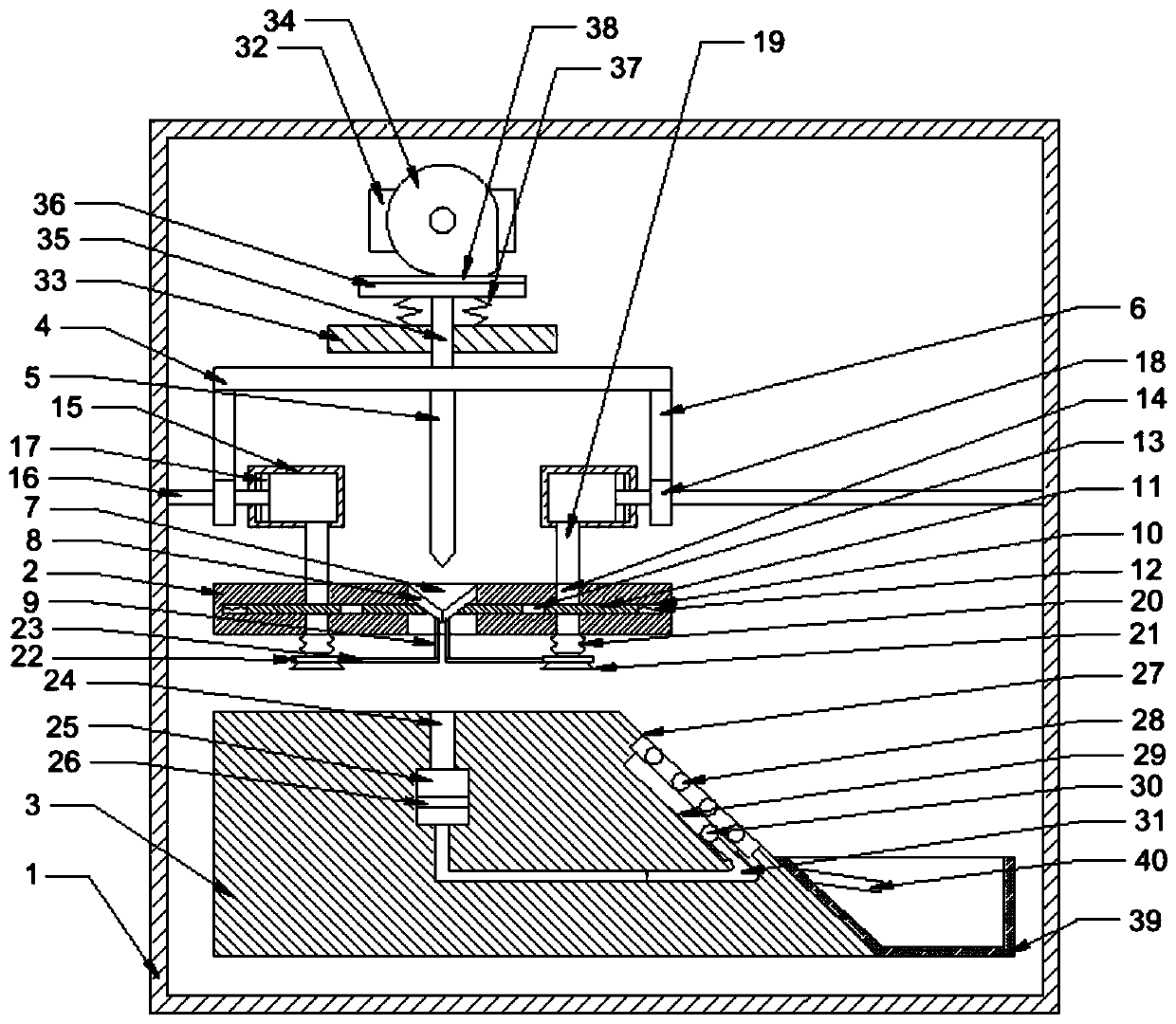
[0019] The reference signs in the accompanying drawings of the specification include: box body 1, limiting plate 2, carrying platform 3, linkage plate 4, cutting knife 5, rack 6, cutting hole 7, limiting plate 8, tie rod 9, transverse groove 10 , Transverse block 11, first spring 12, first through hole 13, second through hole 14, cylinder 15, round shaft 16, fan blade 17, gear 18, air pipe 19, bellows 20, suction cup 21, collar 22 , side rod 23, cutting groove 24, piston chamber 25, piston plate 26, groove 27, bearing shaft 28, inclined groove 29, push shaft 30, strip air bag 31, motor 32, fixed plate 33, cam 34, push Rod 35, push plate 36, second spring 37, rubber layer 38, collection box 39, guide plate 40.

[0020] The embodiment is basically as attached figure 1 As shown: the cutting equipment for bills, including a box body 1, in which a vertical reciprocating mechanism, a limiting plate 2...


PUM


Abstract

The invention discloses cutting equipment for bills. The cutting equipment for bills comprises a box body, wherein a vertical reciprocating mechanism, a limit plate and a bearing table are arranged onthe box body; a cutting knife is arranged on the vertical reciprocating mechanism; a cutting hole is formed in the middle part of the limit plate, and limit sheets are hinged to the inner wall of thecutting hole in the form of left-right symmetry; transversal grooves are formed in the limit plate in the form of left-right symmetry, a transversal block is slidably connected into each transversalgroove, and a first spring is arranged between each transversal block and the corresponding transversal groove; a cutting groove is formed in the bearing table; a piston chamber is formed in the bearing table, and a piston plate is slidably connected into the piston chamber; a groove is formed in the inclined surface of the bearing table, and a plurality of bearing shafts are rotationally connected between the inner walls of the two sides of the groove; an inclined groove is formed in the bottom of the groove, and a push shaft is arranged in the inclined groove; and a strip-shaped air bag abutted against the push shaft is formed in the inclined groove, and communicates with the piston chamber. According to the scheme, the problem that bills are easily damaged due to the cutting of the present bill cutting mechanism is mainly solved.

Description

technical field [0001] The invention relates to the technical field of bill management supporting equipment. Background technique [0002] Bills are paper prints of a certain size, including tax invoices. Common bills are usually printed in multiple continuous strips and in a roll shape. The perforations punched out between each sheet form a cutting line or an integrated structure. The mechanism cuts the two connected bills apart. [0003] At present, the cutting mechanism on the market mainly uses the cutting knife to complete the cutting of the bill; but in the actual operation process, since there is no limit mechanism for the position of the bill in the cutting mechanism, the bill may be misaligned when the cutting knife cuts the bill. Moreover, the bills will stay in place after cutting, causing the accumulation of bills, and even extruding the uncut bills to make them move, which will also cause damage to the bills. Contents of the invention [0004] The present i...

Claims


Application Information

Patent Timeline
Patent Type & Authority Patents(China)
IPC IPC(8): B26D1/08B26D5/08B26D5/16B26D7/00B26D7/02B26D7/08B26D7/32
CPCB26D1/085B26D5/086B26D5/16B26D7/0006B26D7/018B26D7/088B26D7/32B26D2007/322
Inventor 吴仁本
Owner 重庆华康印务有限公司
Why Eureka
Try Eureka