Supercharge Your Innovation With Domain-Expert AI Agents!

Multi-level dissolving-out tank structure for extracting coal ash

An alumina, multi-level technology, applied in the direction of alumina/aluminum hydroxide, etc., can solve the problems of trouble to take out, affect the refining of alumina, cannot be completely dissolved in water, etc., to achieve the effect of easy access and placement

Pending Publication Date: 2018-09-04
HUAIBEI NORMAL UNIVERSITY
View PDF8 Cites 0 Cited by
  • Summary
  • Abstract
  • Description
  • Claims
  • Application Information

AI Technical Summary

Problems solved by technology

[0002] With the steady development of my country's energy industry and the rapid development of the power industry, the discharge of fly ash has increased sharply. Many oxidized components of fly ash can be used as resources, from which we can extract alumina materials. However, in the process of extracting alumina, the water-soluble substances are extracted first, otherwise it will affect the refining of alumina. Most of the common devices for extracting the aqueous solution substances in fly ash are a simple container, and then the treated The fly ash and water are directly poured into the container for water fusion. Since the fly ash is directly poured into the container, the fly ash and water are in a static state in the container, and the fly ash at the bottom of the container is not easy to be fully mixed with water. contact, the water-soluble substances inside the fly ash cannot be completely dissolved in water, and it is troublesome to take the fly ash out of the container, so we propose a method for extracting alumina from fly ash The multi-level dissolution tank structure

Method used


Image

  • Multi-level dissolving-out tank structure for extracting coal ash
  • Multi-level dissolving-out tank structure for extracting coal ash
  • Multi-level dissolving-out tank structure for extracting coal ash

Examples


Embodiment Construction

[0022] The following will clearly and completely describe the technical solutions in the embodiments of the present invention with reference to the accompanying drawings in the embodiments of the present invention. Obviously, the described embodiments are only some, not all, embodiments of the present invention. Based on the embodiments of the present invention, all other embodiments obtained by persons of ordinary skill in the art without making creative efforts belong to the protection scope of the present invention.

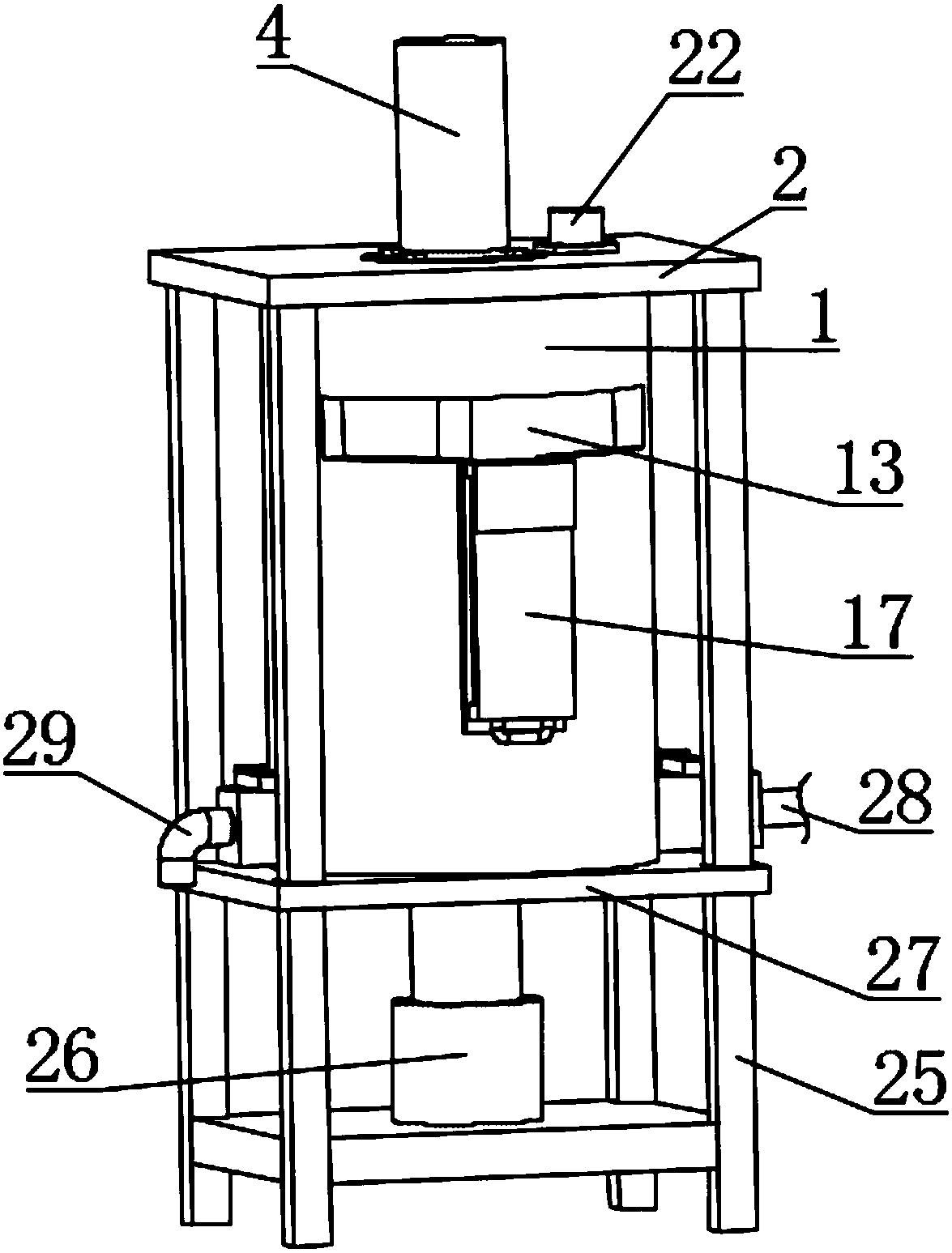
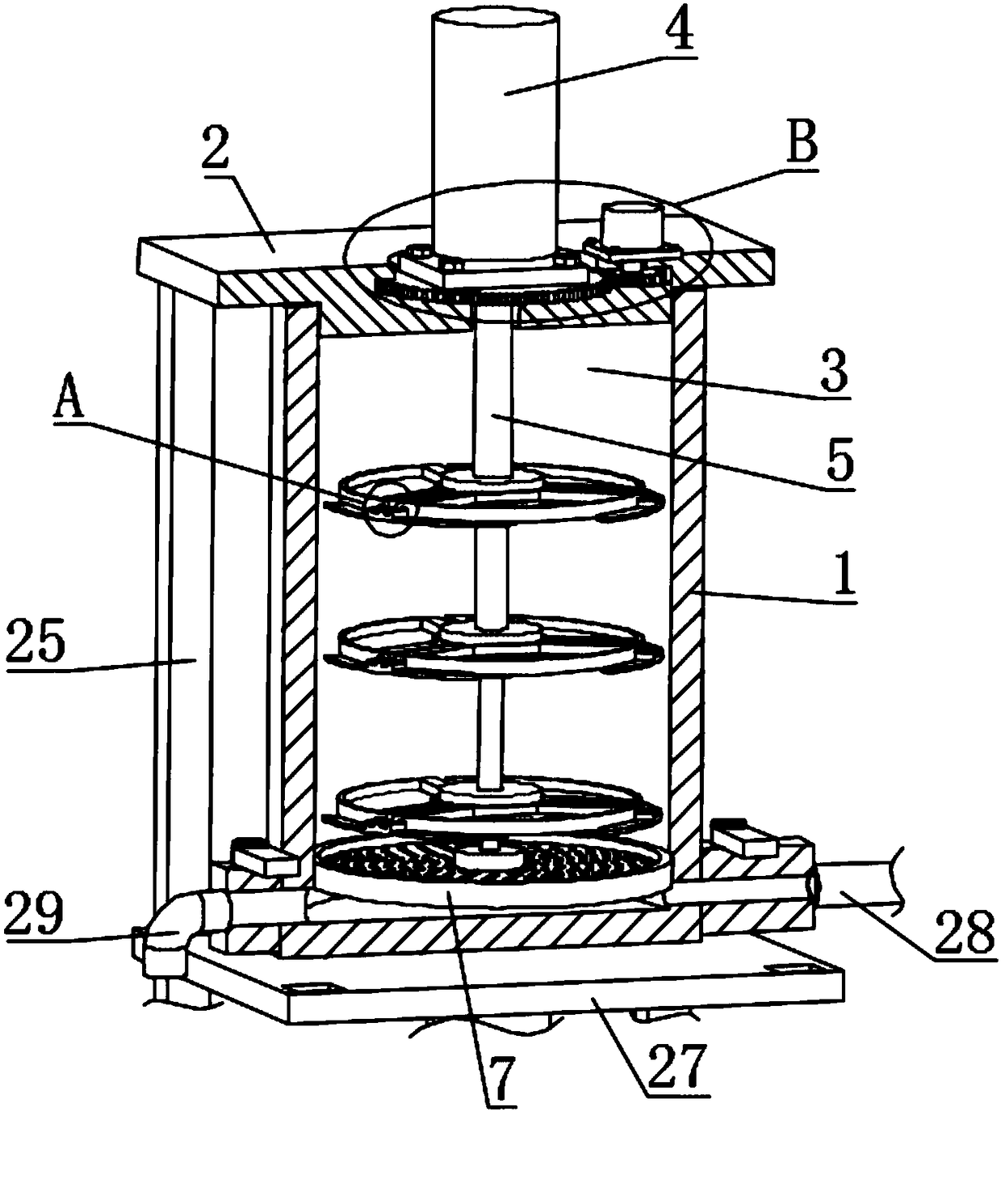
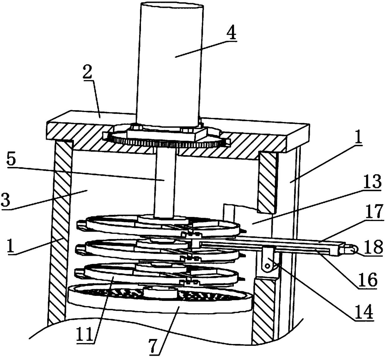
[0023] see Figure 1-9 , the present invention provides a technical solution: a multi-level dissolution tank structure for extracting alumina from fly ash, including a melting tank 1, the inside of the melting tank 1 is provided with a cavity 3, and the inside of the cavity 3 can be Filled with water, the side wall of the melting tank 1 below the inlet and outlet 13 is sealed and can withstand a certain pressure. The upper side of the cavity 3 is movably conne...


PUM


Abstract

The invention discloses a multi-level dissolving-out tank structure for extracting coal ash. The multi-level dissolving-out tank structure comprises a dissolving tank, wherein a cavity is formed in the dissolving tank, a cover plate is movably clamped to the upper side of the cavity, a rotating cavity is formed in the cover plate, a first gear is rotationally connected to the inside of the rotating cavity, an oil cylinder is fixedly connected to the upper side of the first gear, and a telescopic rod is connected to the inside of the oil cylinder in a sliding manner; and inlet / outlet is formedin the side wall of the dissolving tank, a rotating block is rotationally connected to the side wall of the inlet / outlet through a rotating shaft, a sliding chute is formed in the rotating block, a sliding strip is connected to the inside of the sliding chute in a sliding manner, and sliding plate is fixedly connected to the side wall of the sliding strip. According to the multi-level dissolving-out tank structure, the insides of trays in the cavity are placed in a layering manner by virtue of a support block and a support plate, coal ash for extracting aluminum oxide is put into each tray layer by layer and is not integrally stacked together, so that the coal ash in the trays can be in adequate contact with water in the cavities.

Description

technical field [0001] The invention relates to the technical field of dissolution equipment, in particular to a multi-level dissolution tank structure for extracting alumina from fly ash. Background technique [0002] With the steady development of my country's energy industry and the rapid development of the power industry, the discharge of fly ash has increased sharply. Many oxidized components of fly ash can be used as resources, from which we can extract alumina materials. However, in the process of extracting alumina, the water-soluble substances are extracted first, otherwise it will affect the refining of alumina. Most of the common devices for extracting the aqueous solution substances in fly ash are a simple container, and then the treated The fly ash and water are directly poured into the container for water fusion. Since the fly ash is directly poured into the container, the fly ash and water are in a static state in the container, and the fly ash at the bottom of ...

Claims


Application Information

Patent Timeline
Patent Type & Authority Applications(China)
IPC IPC(8): C01F7/02
CPCC01F7/02
Inventor 刘飞王馨
Owner HUAIBEI NORMAL UNIVERSITY
Features
  • R&D
  • Intellectual Property
  • Life Sciences
  • Materials
  • Tech Scout
  • Unparalleled Data Quality
  • Higher Quality Content
  • 60% Fewer Hallucinations
Learn More