
Counterweight adjusting device, built-in manipulating handle and hollow window shutter

A technology for adjusting devices and blinds, which is applied to door/window protection devices, windows/doors, building components, etc., which can solve problems such as inconvenient installation, poor customer experience, hanging down phenomenon, etc. Effect

Pending Publication Date: 2018-09-04
肖敏
View PDF9 Cites 2 Cited by
  • Summary
  • Abstract
  • Description
  • Claims
  • Application Information

AI Technical Summary

Problems solved by technology

[0003] Since hollow louvered glass windows mostly adopt a closed structure, it is difficult to overhaul the built-in venetian blind and its control mechanism, so the stability requirements for the built-in venetian blind and its control mechanism are extremely high
[0004] However, the following problems have been puzzling users of hollow shutters
[0005] First, because the external control handle controls the built-in control handle through the magnetic force of the magnet, if the magnetic force is too large, the adsorption force between the two will be too strong, resulting in a large friction between the control handle and the glass, making consumption It is extremely difficult for the operator to control the blinds, requiring a lot of force to complete the operation, and the customer experience is extremely poor
[0006] Second, if the above-mentioned magnetic force is too small, or the magnetic force gradually disappears during use, it will often cause the handle magnet to demagnetize, which in turn will cause the phenomenon of rebound and hanging down of the venetian blind
[0007] Third, in the prior art, a configuration block is fixed at the lower end of the built-in control handle to solve the above problems, but the counterweight block and the handle are fixedly connected, which makes it inconvenient to install between the two, and cannot be flexibly adjusted according to Need to decide whether to install counterweight

Method used


Image

  • Counterweight adjusting device, built-in manipulating handle and hollow window shutter
  • Counterweight adjusting device, built-in manipulating handle and hollow window shutter
  • Counterweight adjusting device, built-in manipulating handle and hollow window shutter

Examples


Embodiment Construction

[0027] In order to make the purpose and technical solutions of the embodiments of the present invention more clear, the technical solutions of the embodiments of the present invention will be clearly and completely described below in conjunction with the drawings of the embodiments of the present invention. Apparently, the described embodiments are some, not all, embodiments of the present invention. Based on the described embodiments of the present invention, all other embodiments obtained by persons of ordinary skill in the art without creative efforts shall fall within the protection scope of the present invention.

[0028] Those skilled in the art can understand that, unless otherwise defined, all terms (including technical terms and scientific terms) used herein have the same meaning as commonly understood by those of ordinary skill in the art to which this invention belongs. It should also be understood that terms such as those defined in commonly used dictionaries shoul...


PUM


Abstract

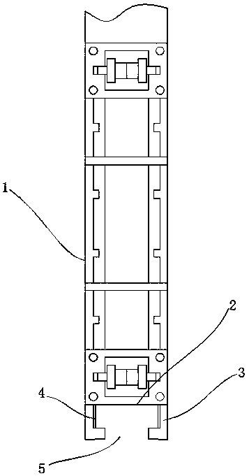
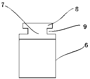
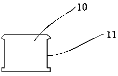
The invention relates to a counterweight adjusting device used for a built-in manipulating handle of a hollow window shutter. The built-in manipulating handle comprises a handle body; the counterweight adjusting device comprises cantilevers arranged on the left side and the right side of the bottom of the handle body, and a clamping groove structure is formed between the cantilevers on the left side and the right side and the bottom of the handle body; the counterweight adjusting device further comprises a counterweight block adjustment device; the counterweight block adjustment device comprises a clamping buckle arranged at the top end of the counterweight block adjustment device, and mounting grooves are formed in the left side and the right side of the clamping buckle; and the clampingbuckle can be mounted in the clamping groove structure in a matched mode, the bottom ends of the cantilevers are mounted in the mounting grooves of the clamping buckle. In order that shutter blinds are retracted and pulled more easily and the phenomena that the shutter blinds rebound and are hung downwards due to degaussing of a handle magnet are prevented, the counterweight adjusting device is adopted. A lead block with the weight being similar to the weight of blades is additionally arranged on the lower portion of the inner handle, the gravity of the blades is balanced under the situation that magnetic force is weakened, and meanwhile, the labor saving effect is achieved; and the built-in handle and a counterweight block are connected by adopting the clamping groove structure, mountingis convenient, and falling-off is not prone to occurring.

Description

technical field [0001] The invention belongs to the technical field of glass windows, and in particular relates to a counterweight adjustment device, a built-in control handle and a hollow shutter. Background technique [0002] Hollow shutter glass has been widely used, and its good thermal insulation and sound insulation properties are favored by the people. The existing hollow louvered glass windows often use an external control handle to control the built-in control handle. Through the gravitational force between the magnets installed on the external control handle and the built-in control handle respectively, the external control handle controls the up and down of the built-in control handle. move. The existing external control handle has the following problems. [0003] Since hollow louvered glass windows mostly adopt a closed structure, it is difficult to overhaul the built-in venetian blind and its control mechanism, so the stability requirements for the built-in ve...

Claims


Application Information

Patent Timeline
IPC IPC(8): E06B9/322E06B9/264
CPCE06B9/264E06B9/322
Inventor 肖敏
Owner 肖敏
Learn More