Valve fastening device and use method thereof

A technology for fastening devices and valves, applied in valve devices, valve operation/release devices, valve details, etc., can solve problems such as hindering staff walking and inconvenient valve operation, so as to improve traffic smoothness and ensure normal use , the effect of convenient operation

Pending Publication Date: 2018-09-04
QINZHOU UNIV
View PDF8 Cites 0 Cited by
  • Summary
  • Abstract
  • Description
  • Claims
  • Application Information

AI Technical Summary

Problems solved by technology

[0003] The invention proposes a valve fastening device and its use method, which solves the problems in the prior art that the valve is inconvenient to operate and hinders the staff from walking

Method used


Image

  • Valve fastening device and use method thereof
  • Valve fastening device and use method thereof
  • Valve fastening device and use method thereof

Examples


Embodiment 1

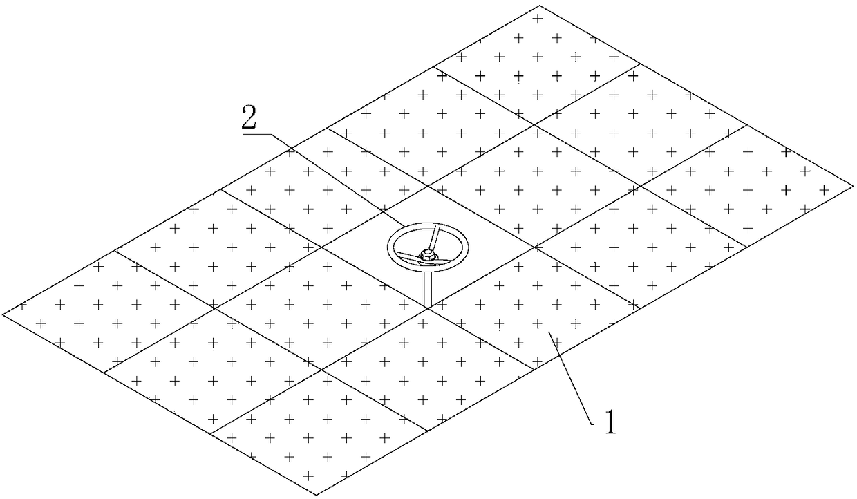
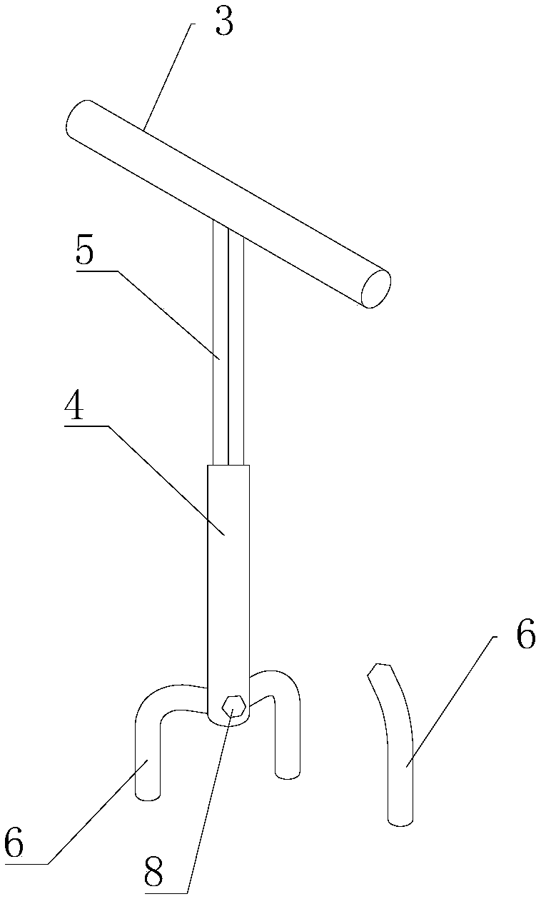
[0029] Such as figure 1 As shown, it is a schematic diagram of the position and structure between the flower iron plate 1 and the valve 2 under normal conditions. At this time, the height of the valve 2 is consistent with the height of the flower iron plate 1, which is very inconvenient for workers to operate the valve 2. figure 2 It is an embodiment of the valve fastening device of the present invention. For the convenience of description, one of the fixing forks 6 is separated in the figure. This embodiment includes a turning handle 4, a turning shaft 5 and a fixing fork 6, wherein the turning handle 4 It is fixed on the upper end of the rotating shaft 5 and arranged perpendicular to it. The two can be directly welded and fixed, or can be fixed by other methods. It is necessary to ensure that the rotating shaft 5 can rotate synchronously when the rotating handle 4 is rotated. In terms of length, the turning handle 4 can be selected to be 200mm, and the turning shaft 5 can b...

Embodiment 2

[0034] The present invention also proposes a method for using a valve fastening device, comprising the following sequential steps:

[0035] S1. Select a suitable length of the rotating shaft according to the height of the valve;

[0036] S2. Select a suitable number of fixed forks according to the shape of the valve, and insert the non-circular ends of the above fixed forks into the limit holes at the lower end of the rotating shaft in sequence;

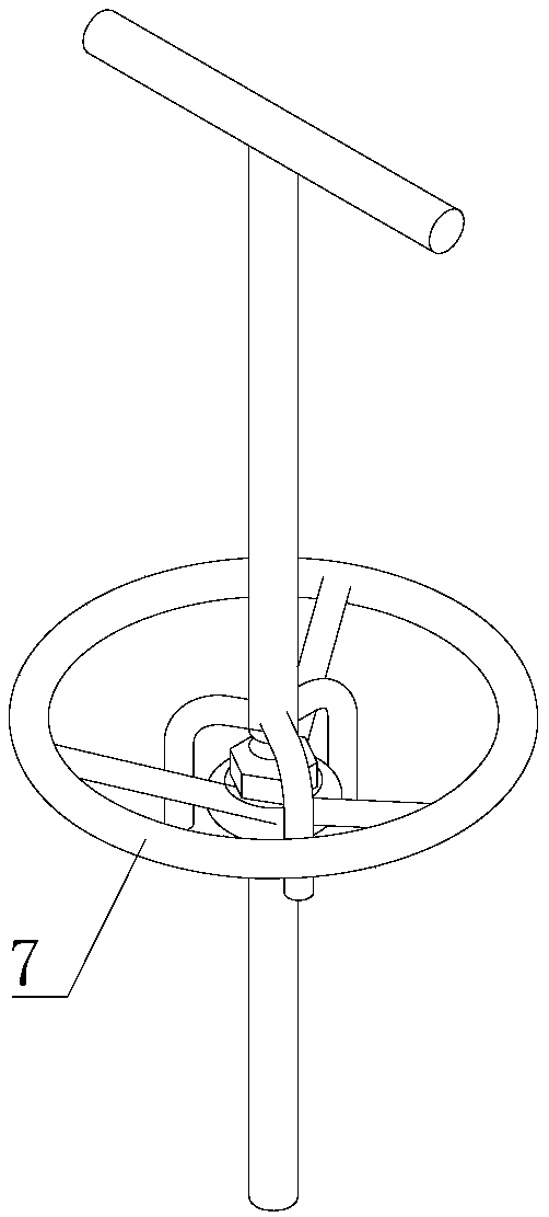
[0037] S3. Put the above device in the middle of the valve, so that the fixed fork is inserted into the hand wheel of the valve at intervals;

[0038] S4. Rotate the turning handle on the upper end of the rotating shaft clockwise or counterclockwise to realize the closing or opening of the valve;

[0039] S5. After the operation is completed, remove the device from the valve, pull out all the fixing forks from the limiting holes and put all the parts back in place for the next use.

[0040] In the above step S4, during the rotation...


PUM


Abstract

The invention provides a valve fastening device and a use method of the valve fastening device. The valve fastening device solves the problems that in the prior art, a valve is inconvenient to operateand hinders walk of staff. The valve fastening device comprises a rotating handle, a rotating shaft and multiple fixing forks. The rotating handle is fixed to the upper end of the rotating shaft andis perpendicular to the rotating shaft. The connection point between the rotating shaft and the rotating handle is located in the middle of the rotating handle. The extension direction of the rotatingshaft and the extension direction of a valve transmission shaft are identical. The fixing forks are arranged at the lower end of the rotating shaft. Each fixing fork is in an L shape, wherein one side of the L-shaped fixing fork is perpendicularly connected to the rotating shaft, and the other side of the L-shaped fixing fork is parallel to the rotating shaft and extends downwards. The L-shaped fixing forks are inserted into a hand wheel of the valve. The rotating handle is rotated to switch on or switch off the valve.

Description

technical field [0001] The invention relates to the technical field of mechanical fasteners, in particular to a valve fastening device with simple structure and convenient use and a use method thereof. Background technique [0002] In the engine room of ships and offshore platforms, valves are very common components. In order to avoid hindering the walking of people on the ship platform, when arranging and installing valves, they can only be arranged flush with the flower iron plate (such as figure 1 shown). This has caused operational difficulties. When people need to open or close the valve, because the valve is flush with the flower iron plate, and people are standing on the flower iron plate to operate, the operation is very inconvenient, and it is impossible to open or close the valve. Effect. Sometimes, in order to facilitate people's operation, the transmission shaft of the valve has to be reprocessed, and the small shaft of the valve is extended to make the valve a...

Claims


Application Information

Patent Timeline
Patent Type & Authority Applications(China)
IPC IPC(8): F16K31/60
CPCF16K31/60
Inventor 焦自权冯志强王侨孙勇敢焦子硕吕娜韩鑫夏义江杨润党石南辉黄新欢
Owner QINZHOU UNIV
Why Eureka
Try Eureka