Two-stage compression refrigerating system

A refrigeration system and two-stage compression technology, which is applied in the direction of compressors, refrigerators, compressors, etc., can solve the problems of low performance coefficient of single-stage compression refrigeration cycle, large wear degree of compressor, complex structure of refrigeration system, etc., and achieve reduction The effect of input cost, gas specific gravity reduction, and high energy efficiency ratio of the system

Pending Publication Date: 2018-09-04
天津市正源制冷设备有限公司
View PDF0 Cites 3 Cited by
  • Summary
  • Abstract
  • Description
  • Claims
  • Application Information

AI Technical Summary

Problems solved by technology

This temperature requirement has the following disadvantages for the application of single-stage compression refrigeration cycle: the compressor works for a long time between a large working pressure difference, which consumes a lot of power and wears the compressor greatly, resulting in the performance of the single-stage compression refrigeration cycle. The coefficient is relatively low and the maintenance cost is high
This temperature requirement has the following disadvantages for the two-stage compression refrigeration cycle: the structure of the refrigeration system is complex and the input cost is high, so it is very necessary to optimize the two-stage compression refrigeration cycle system
Both the single-stage compression refrigeration system and the two-stage compression refrigeration system have the following disadvantages: the throttling process of the throttling and step-down element has a large loss, resulting in a large increase in the entropy of the entire refrigeration cycle and a low performance coefficient of the system.

Method used


Image

  • Two-stage compression refrigerating system

Examples


Embodiment Construction

[0022] The present invention will be further described below with reference to specific embodiments.

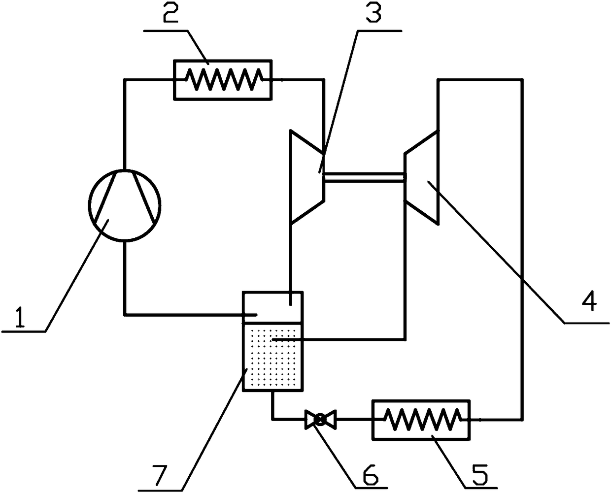
[0023] The principle diagram of a two-stage compression refrigeration system with an expander according to the present invention is as follows: figure 1 As shown, a functional compressor 1 , a condenser 2 , an expander 3 , a booster compressor 4 , an evaporator 5 , a throttling element 6 and a receiver 7 are included. The exhaust port of the functional compressor 1 is connected to the inlet of the condenser 2, the outlet of the condenser 2 is connected to the inlet end of the expander 3, and the outlet end of the expander 3 is connected to the receiver. The gas-liquid inlet of the receiver 7 is connected, the liquid outlet of the receiver 7 is connected to the inlet of the evaporator 5 through the throttling element 6, and the outlet of the evaporator 5 is connected to the suction of the booster compressor 4. The gas port is connected, the exhaust port of the booster compres...


PUM


Abstract

The invention discloses a two-stage compression refrigerating system which is a system aiming at reducing losses in the throttling process and improving the system energy efficiency. The exhaust portof a function compressor is connected with the inlet of a condenser, the outlet of the condenser is connected with the inlet end of an expansion machine, the outlet end of the expansion machine is connected with the gas-liquid inlet of a receiver, the liquid outlet of the receiver is connected with the inlet of an evaporator through a restricting element, the outlet of the evaporator is connectedwith the air sucking opening of a booster compressor, the exhaust opening of the booster compressor is connected with the gas inlet of the receiver, the gas outlet of the receiver is connected with the air sucking opening of the function compressor, and the booster compressor is driven by the expansion machine. By means of the system, the expansion machine expands to act to drive the booster compressor to run, the losses of the throttling process are reduced, and the energy efficiency ratio of a refrigerating cycle is improved. Meanwhile, compressor liquid hammering caused by unbalanced liquidsupply amount and evaporation capacity in the evaporator is avoided, and the maintaining cost is reduced. In addition, the structure is simple, installation is convenient, and cost is low.

Description

technical field [0001] The invention relates to the technical field of refrigeration, in particular to a two-stage compression refrigeration system with an expander. Background technique [0002] When lower temperature refrigeration is required, a single-stage compression or two-stage compression refrigeration cycle is usually used. This temperature requirement has the following disadvantages for the application of single-stage compression refrigeration cycle: the compressor works between large working pressure differences for a long time, which consumes a lot of power and wears the compressor to a large degree, resulting in the performance of the single-stage compression refrigeration cycle. The coefficient is relatively low and the maintenance cost is high. This temperature requirement has the following shortcomings for the dual-stage compression refrigeration cycle: the refrigeration system has a complex structure and high investment cost, so it is very necessary to opti...

Claims


Application Information

Patent Timeline
Patent Type & Authority Applications(China)
IPC IPC(8): F25B1/10F25B31/00
CPCF25B1/10F25B31/00
Inventor 罗永生
Owner 天津市正源制冷设备有限公司
Why Eureka
Try Eureka