
Safety power distribution method for civil use

A safe and civil technology, applied in the substation/distribution device casing, electrical components, substation/switch layout details, etc., can solve problems such as damage to electrical equipment and power supply equipment, power distribution cabinet open circuit, short circuit, etc., to reduce work volume, simple operation, and the effect of saving wires

Inactive Publication Date: 2018-09-04
陈二东
View PDF5 Cites 2 Cited by
  • Summary
  • Abstract
  • Description
  • Claims
  • Application Information

AI Technical Summary

Problems solved by technology

[0002] In today's society, people's production and life are closely related to electric energy, and people's clothing, food, housing and transportation are inseparable from electric energy. However, in some factories or counties with a lot of dust, electrical equipment is easily polluted by dust, thus damaging electrical equipment. and power supply equipment, it also brings a lot of inconvenience to people's daily life; among them, the impact on the power distribution cabinet is extremely prominent. Difficulty in using electricity; In view of this, the present invention provides a kind of method for civilian safe power distribution, which has the following characteristics:

Method used


Image

  • Safety power distribution method for civil use
  • Safety power distribution method for civil use
  • Safety power distribution method for civil use

Examples


Embodiment Construction

[0030] In order to make the technical means, creative features, goals and effects achieved by the present invention easy to understand, the present invention will be further described below in conjunction with specific embodiments.

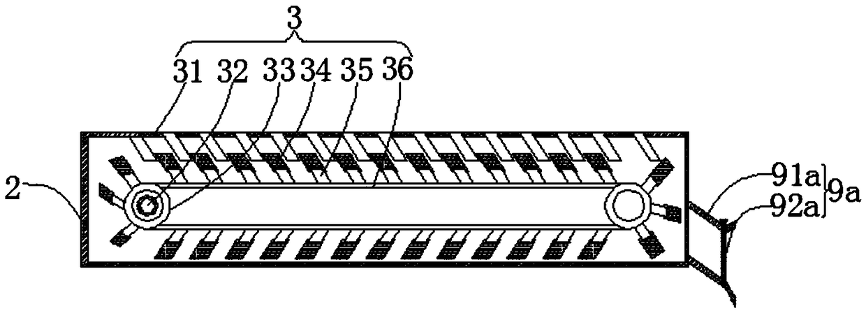
[0031] Such as figure 1 and figure 2 As shown in the present invention, a method for civil safe power distribution, the method includes the following steps:

[0032] s1: Connect the power supply line to the anti-aging power distribution cabinet;

[0033] s2: Connect the leakage protector with the anti-aging power distribution cabinet;

[0034] s3: connect the anti-aging power distribution cabinet in s2 to the output device;

[0035] s4: Anti-aging power distribution cabinet supplies power to output devices;

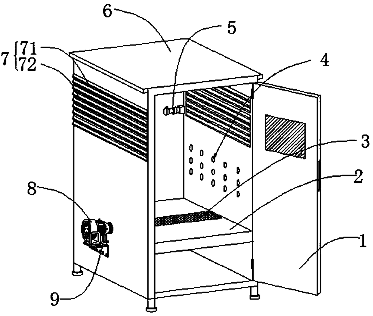
[0036] Among them, the method adopts anti-aging power distribution cabinet including cabinet door 1, fixed plate 2, dust removal mechanism 3, switch installation hole 4, wire release mechanism 5, cabinet body 6, heat dissipation mechanism ...


PUM


Abstract

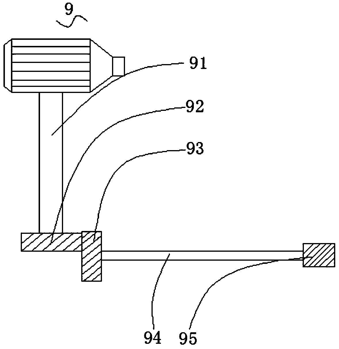
The invention relates to the field of power distribution cabinets, in particular to a safety power distribution method for civil use, comprising the steps from s1 to s4. The safety power distributionmethod for civil use adopts an anti-aging power distribution cabinet, wherein the anti-aging power distribution cabinet comprises a cabinet door, a fixed plate, a dust removing mechanism, switch mounting holes, a pay-off mechanism, a cabinet body, a heat dissipation mechanism, a fan, a transmission mechanism and a discharging mechanism. The pay-off mechanism used for preventing maintenance personnel from having insufficient electric wires during maintenance and providing the electric wires for maintenance is arranged inside the cabinet body, the electric wire on the surface of a rotating shaftis pulled to drive a fluted disc in a fixed disc to rotate, the interior of the fixed plate is rotatably connected with the dust removing mechanism so as to collect dust inside the fixed plate, the transmission mechanism is driven after the fan rotates, the transmission mechanism drives the dust removing mechanism inside the fixed plate to rotate, thus the fan blows out the collected dust, and asloping plate is arranged on the inner top surface of the fixed plate obliquely, thereby avoiding the dust from entering the cabinet body when the fan handles the dust.

Description

technical field [0001] The invention relates to the field of power distribution cabinets, in particular to a civil safe power distribution method. Background technique [0002] In today's society, people's production and life are closely related to electric energy, and people's clothing, food, housing and transportation are inseparable from electric energy. However, in some factories or counties with a lot of dust, electrical equipment is easily polluted by dust, thus damaging electrical equipment. and power supply equipment, it also brings a lot of inconvenience to people's daily life; among them, the impact on the power distribution cabinet is extremely prominent. Difficulty in using electricity; In view of this, the present invention provides a kind of method for civilian safe power distribution, which has the following characteristics: [0003] (1) A kind of civil safety power distribution method described in the present invention, this method adopts the inside of the c...

Claims


Application Information

Patent Timeline
Patent Type & Authority Applications(China)
IPC IPC(8): H02B1/30H02B1/28H02B1/56
CPCH02B1/30H02B1/28H02B1/565
Inventor 陈二东朱继鹏
Owner 陈二东
Learn More