Device for electrically disassembling stator winding of motor

A motor stator and electric technology, applied in the field of disassembly tools, can solve the problems of inconvenient operation, inability to relatively improve work efficiency, delay in disassembly work time, etc., and achieve the effect of convenient disassembly and use

Inactive Publication Date: 2018-09-04
XIANGTAN UNIV
View PDF7 Cites 20 Cited by
  • Summary
  • Abstract
  • Description
  • Claims
  • Application Information

AI Technical Summary

Problems solved by technology

There is no special tool for the disassembly of the existing stator windings. The current stator winding drawing tools and fixing fixtures are in a separate structure. The copper coil of the winding is pulled out. Due to the fact that the fixture for fixing the stator and the drawing tool are in a separated state and its structure is limited, the operation is extremely inconvenient in actual work. After the stator is fixed by the fixing fixture, the drawing tool is fixed around the fixing fixture. , to enter the process of drawing the copper coil of the winding. Moreover, after the drawing head of the existing drawing tool pulls out one of the multi-turn windings of the stator winding, it is necessary to loosen the fixing fixture to rotate the stator at a certain angle and then fix it again. , align the other winding with the pulling head of the pulling tool, and then operate the pulling head of the pulling tool to pull out another winding, and so on, until all the stator copper wire windings are pulled out, because, The drawing head of the drawing tool needs to fix the stator with a fixing mechanism before pulling out a circle of winding, so the operation is extremely inconvenient, and the work efficiency cannot be relatively improved; another way is that the user constantly adjusts the pulling position of the drawing tool during operation. The position of the pulling head is aligned with one winding at a time to pull out. Since it takes a certain amount of time to adjust or fix the pulling head each time, the operation is also very inconvenient, and because the speed of adjusting the position of the pulling head is slow, it will cause disassembly. work time delay

Method used


Image

  • Device for electrically disassembling stator winding of motor
  • Device for electrically disassembling stator winding of motor
  • Device for electrically disassembling stator winding of motor

Examples


Embodiment Construction

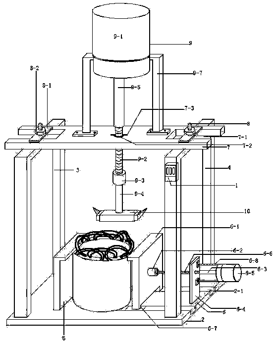
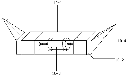
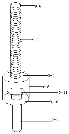
[0019] figure 1 , 2 , 3, a device for electrically dismantling the stator windings of a motor, including a switching power supply module 1 of AC 220V to DC 24V, also has a lower support plate 2, a left vertical plate 3, a right vertical plate 4, a fixed splint 5, an electric Plywood mechanism 6, horizontal support plate 7, upper locking screw 8, electric pull rod mechanism 9, electric pulling head mechanism 10, power switch 11 and component box 12, left vertical plate 3 and right vertical plate 4 are "П" type, The left vertical plate 3 and the lower part of the right vertical plate 4 are respectively welded to the upper parts of the left and right ends of the lower support plate 2, and the right part of the lower support plate 2 has a chute 2-1 horizontally from the front to the rear. The fixed splint 5 is " ┌” type, the lower part of the fixed splint 5 is welded on the left upper part of the lower support plate 2, the fixed splint 5 is located on the right side of the left v...


PUM


Abstract

The invention provides a device for electrically disassembling a stator winding of a motor. The device is composed of a lower supporting plate, a left vertical plate, a right vertical plate, a fixed clamping plate, an electric clamping plate mechanism, a horizontal supporting plate, upper locking screw rods, an electric pulling rod mechanism, an electric drawing head mechanism, a power supply switch and a component box. The left vertical plate and the right vertical plate are respectively installed at the left end and the right end of the lower supporting plate. The fixed clamping plate is installed at the upper left part of the lower supporting plate; the electric clamping plate mechanism is installed at the upper right end of the lower supporting plate; the lower ends of the upper locking screw rods are installed at the middle parts of the upper ends of the left vertical plate and the right vertical plate respectively; the horizontal supporting plate is installed at the left verticalplate and the right vertical plate; the electric pulling rod mechanism is installed at the horizontal supporting plate and is connected with the electric pulling rod mechanism; and the power supply switch is connected with the electric clamping plate mechanism, the electric pulling rod mechanism, and the electric pulling rod mechanism by wires. The device having a simple and compact structure issuitable for dismounting of stator copper wire windings with different diameters. The device is used conveniently; related equipment is driven to work by the motor; and two groups of stator copper wire windings are pulled out simultaneously once.

Description

technical field [0001] The invention relates to the field of dismantling tools, in particular to a device for electrically dismantling motor stator windings. Background technique [0002] In the motor repair industry, waste recycling industry, etc., it is often necessary to disassemble the stator winding of the damaged motor, so as to facilitate the maintenance industry to rewind the new copper wire winding on the stator. The waste recycling industry directly separates the stator from the copper wire winding. Then classified sales. The existing stator winding removal method is mostly to cut off one end of the stator winding with a cutting tool (such as manual steel scissors), and then use wire cutters manually or use a stator winding pulling tool to cut the other end of the stator winding for multiple turns. The windings are pulled out separately. There is no special tool for the disassembly of the existing stator windings. The current stator winding drawing tools and fixi...

Claims


Application Information

Patent Timeline
Patent Type & Authority Applications(China)
IPC IPC(8): H02K15/00
CPCH02K15/0006
Inventor 张建平李云迪刘庭显胡慧瑶
Owner XIANGTAN UNIV
Why Eureka
Try Eureka