
Flow control method for proportional valve of breathing auxiliary device

A technology of breathing assistance and flow control, applied in the direction of respirators, medical equipment, instruments, etc., can solve the problems of poor accuracy, difficult adjustment, and large manpower consumption, so as to achieve the effect of ensuring accuracy

Inactive Publication Date: 2018-09-07
HUNAN MICOME ZHONGJIN MEDICAL SCI & TECH DEV CO LTD
View PDF12 Cites 7 Cited by
  • Summary
  • Abstract
  • Description
  • Claims
  • Application Information

AI Technical Summary

Problems solved by technology

However, due to the nonlinearity and poor repeatability of the electromagnetic proportional valve, the traditional PID closed-loop control scheme is difficult to achieve precise adjustment
Before the product leaves the factory, the supplier needs to accurately calibrate the flow control accuracy of the most electromagnetic proportional valve, and because the consistency of the proportional valve is poor, the calibration process not only needs a lot of manpower and material resources, but also with the aging of the product, the accuracy are also getting worse, which in turn increases maintenance costs
[0003] The flow control method of the proportional valve in the related art is to establish a corresponding relationship curve between the valve current value and the valve output flow, and perform piecewise linear processing on the relationship curve. However, in practical applications, the pressure of the gas source often varies. The simple relationship between valve current and flow is difficult to guarantee the accuracy of the output flow of the electromagnetic proportional valve.

Method used


Image

  • Flow control method for proportional valve of breathing auxiliary device
  • Flow control method for proportional valve of breathing auxiliary device

Examples


Embodiment Construction

[0022] In order to facilitate the understanding of the present invention, the present invention will be described more fully below in conjunction with the examples. Although a preferred embodiment of the present invention is given. However, the present invention can be embodied in many different forms and is not limited to the embodiments described herein. On the contrary, these embodiments are provided to make the understanding of the disclosure of the present invention more thorough and comprehensive.

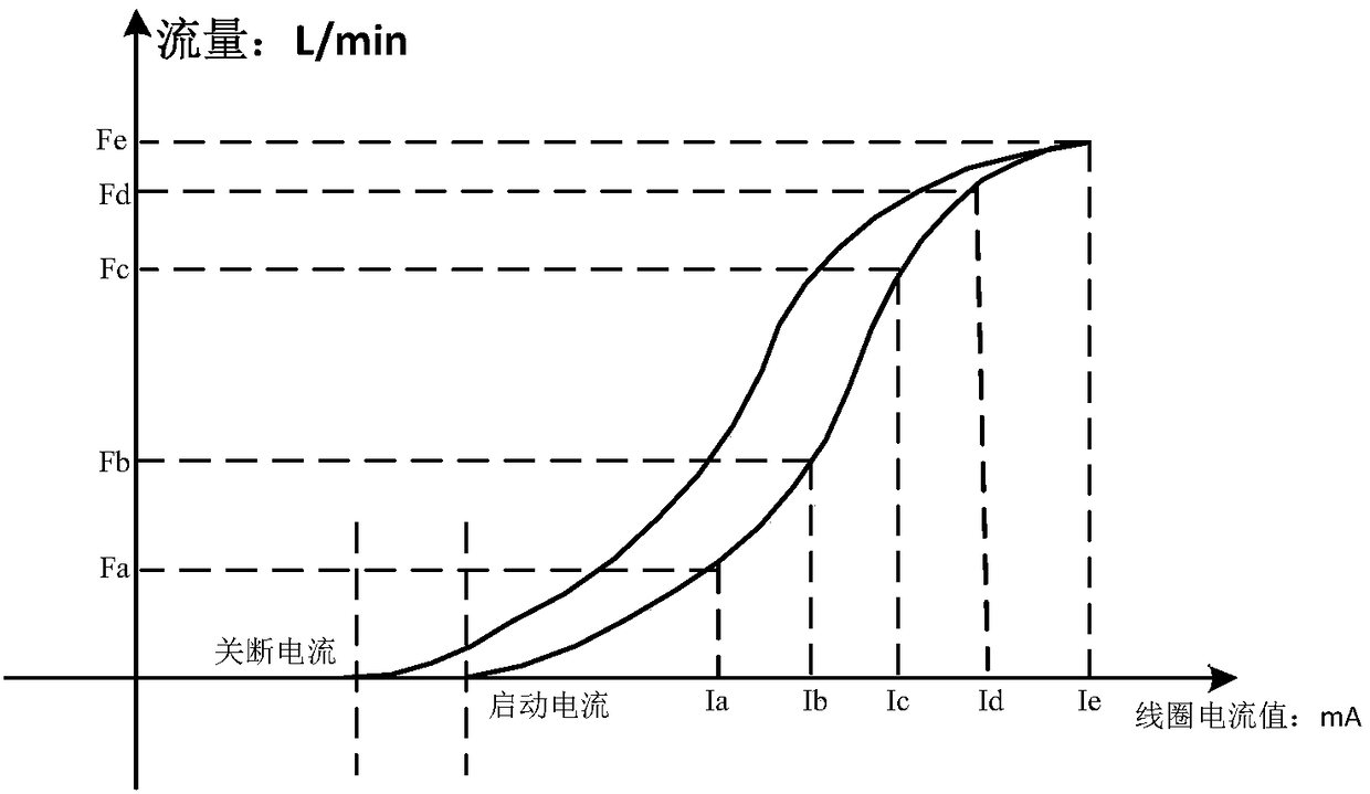
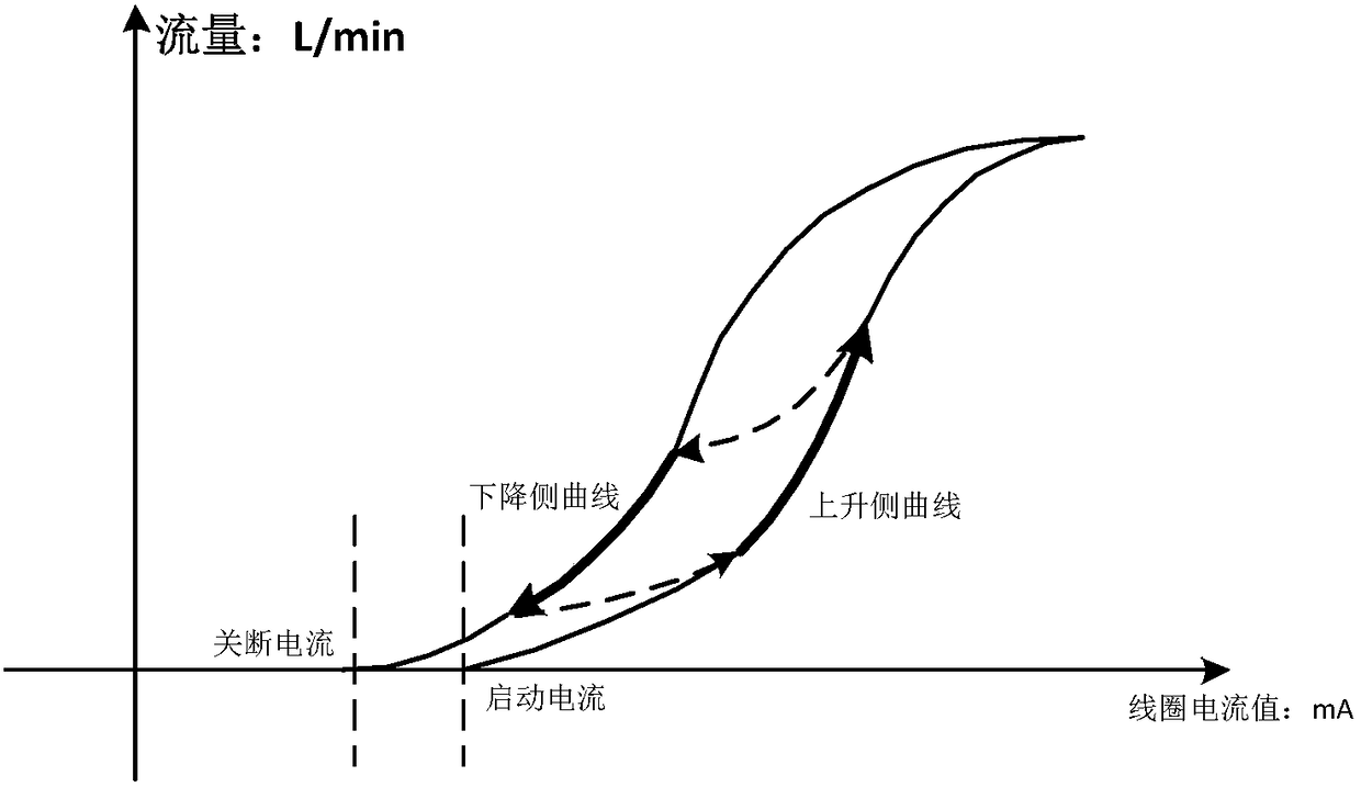
[0023] see figure 1 with figure 2 , the present invention provides a flow control method for a proportional valve of a breathing assistance device, comprising:

[0024] Step 1. Define the fuzzy calibration range, define Is as the start-up current, Id as the shutdown current, Im as the maximum current, introduce the input pressure P, and obtain three current relationships: Is=Is(p); Id=Id(p); Im=Im(p), and the highest flow relationship Fm=Fm(p), where F is the pre-output ...


PUM


Abstract

The invention discloses a flow control method for a proportional valve of a breathing auxiliary device. The flow control method comprises the following steps: S1, defining a fuzzy calibration range, defining Is as the starting current, Id as the turn-off current and Im as the maximum current, introducing in input pressure P, and obtaining three current relationships: Is=IS(p), Id=Id(p), Im=Im(P),and the maximum flow relationship Fm=Fm(p), wherein F is the pre-output flow value; S2, extracting the fuzzy calibration features, and dividing the fuzzy calibration subsets; S3, selecting one sectionat the rising side and one section at the descending side of the work of the proportional valve, and establishing a curve in the shape of two concentric squares with different sizes; and S4, carryingout flow control on the proportional valve according to the established relationship between the output flow and the control current. Compared with the relevant technologies, the flow control methodfor the proportional valve of the breathing auxiliary device has the advantage that the flow control accuracy can be guaranteed.

Description

technical field [0001] The invention relates to the technical field of breathing assistance equipment, in particular to a flow control method of a proportional valve of breathing assistance equipment. Background technique [0002] At present, whether it is an electric ventilator or a pneumatic ventilator, it is necessary to adjust the flow rate of the controlled gas through an electromagnetic proportional valve. However, due to the nonlinearity and poor repeatability of the electromagnetic proportional valve, the traditional PID closed-loop control scheme is difficult to achieve precise adjustment. Before the product leaves the factory, the supplier needs to accurately calibrate the flow control accuracy of the most electromagnetic proportional valve, and because the consistency of the proportional valve is poor, the calibration process not only needs a lot of manpower and material resources, but also with the aging of the product, the accuracy It also keeps getting worse, ...

Claims


Application Information

Patent Timeline
IPC IPC(8): A61M16/20G16H20/00G16H50/00
CPCA61M2205/33A61M16/203G16H20/00G16H50/00
Inventor 戴征李伟利
Owner HUNAN MICOME ZHONGJIN MEDICAL SCI & TECH DEV CO LTD
Learn More