Robot discharge device

A robot and sliding installation technology, applied in the field of robots, can solve the problems of high labor intensity, and achieve the effect of reducing labor intensity, reducing handling intensity and simple structure

Inactive Publication Date: 2018-09-07
清远市校维绘动漫科技有限公司
View PDF0 Cites 3 Cited by
  • Summary
  • Abstract
  • Description
  • Claims
  • Application Information

AI Technical Summary

Problems solved by technology

[0003] The purpose of the present invention is to solve the shortcomings of high labor intensity in the prior art, and propose a robot cutting device

Method used


Image

  • Robot discharge device
  • Robot discharge device
  • Robot discharge device

Examples


Embodiment Construction

[0016] The following will clearly and completely describe the technical solutions in the embodiments of the present invention with reference to the accompanying drawings in the embodiments of the present invention. Obviously, the described embodiments are only some, not all, embodiments of the present invention.

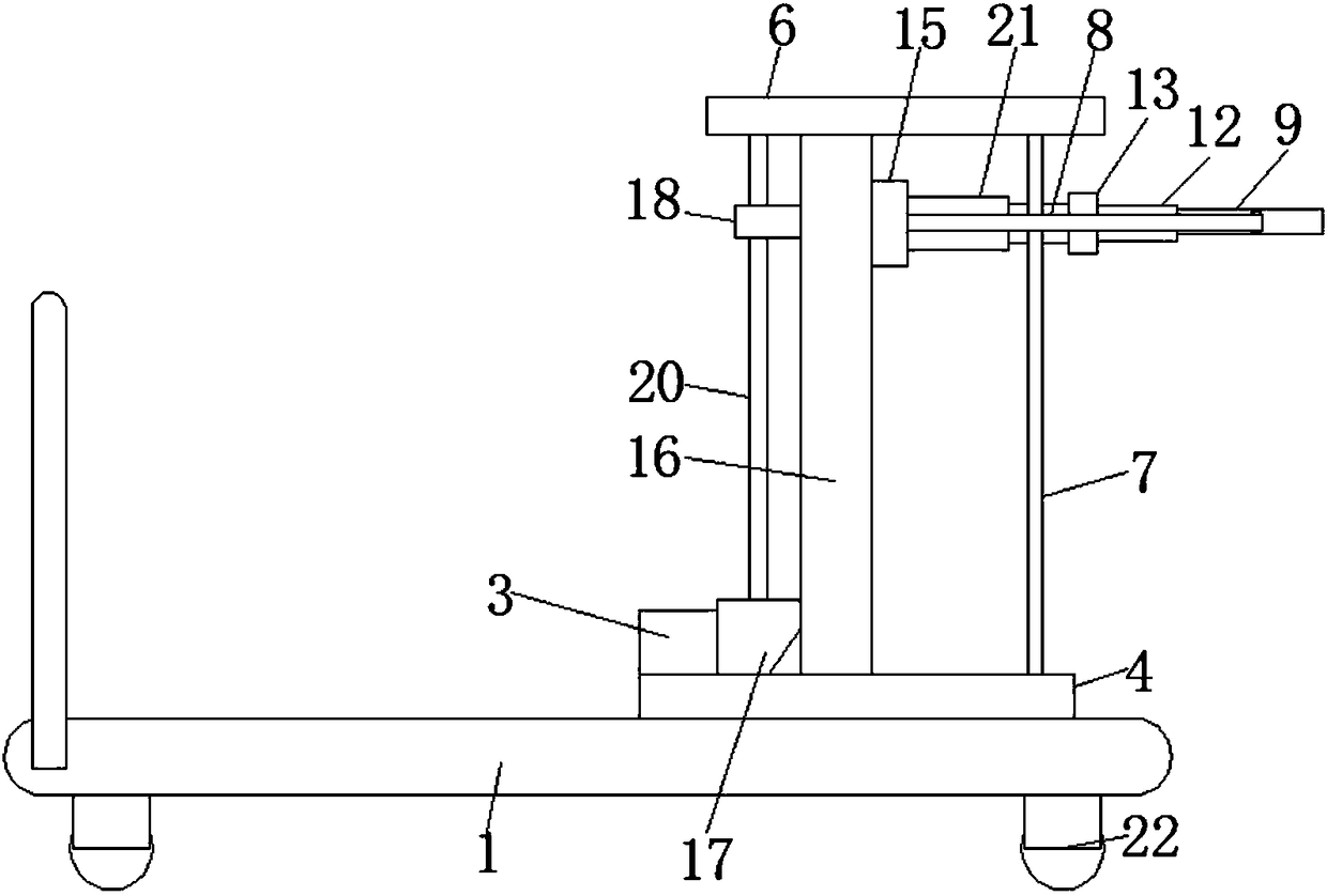
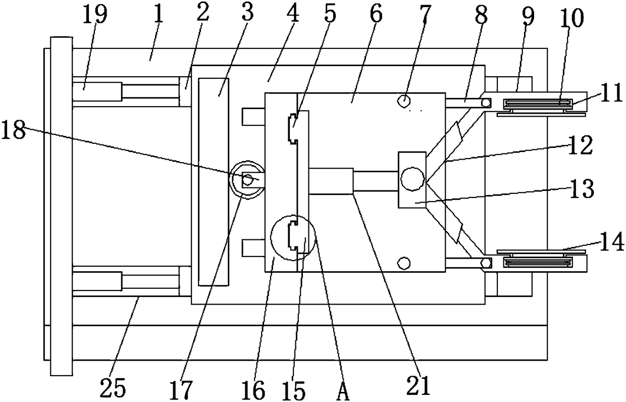
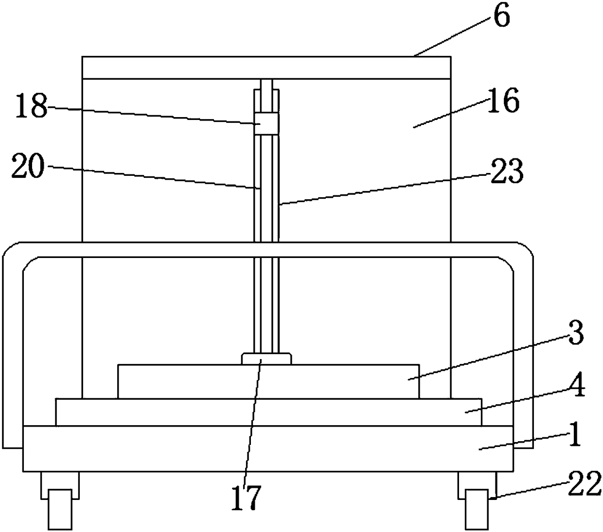
[0017] refer to Figure 1-4 , a robot blanking device, comprising a bottom plate 1, the four corners of the bottom of the bottom plate 1 are rotatably equipped with traveling wheels 22, the traveling wheels 22 are universal wheels with a brake mechanism, and the top end of the bottom plate 1 is fixedly connected with a push handle, the bottom of the bottom plate 1 The upper surface is horizontally provided with two second chute 25, and the inside of the second chute 25 is slidably installed with a sliding seat 2, and a first electric telescopic rod 19 is connected between the end of one end of the sliding seat 2 and the second chute 25. , and the tops of the two slid...


PUM


Abstract

The invention relates to the technical field of robots, in particular to a robot discharge device which comprises a bottom plate. Two second sliding grooves are horizontally formed in the upper surface of the bottom plate, sliding bases are installed inside the second sliding grooves in a sliding mode, first electric telescopic rods are connected between the sliding bases and one ends of the second sliding grooves, the tops of the two sliding bases are jointly connected with a first supporting plate, a second supporting plate is perpendicularly connected to the top of the first supporting plate, a top plate is horizontally connected to the top of the second supporting plate, and a discharge mechanism is arranged between the top plate and the first supporting plate. According to the robot discharge device, the structure is simple, the size is small, use is convenient, the labor intensity of transportation workers is effectively lowered, and meanwhile transportation time is shortened.

Description

technical field [0001] The invention relates to the technical field of robots, in particular to a robot unloading device. Background technique [0002] When the truck is delivering the goods, after arriving at the delivery location, it needs to manually unload the goods on the truck to the ground, and then carry them on the trolley, which not only wastes time, but also increases the labor intensity of the porters. Contents of the invention [0003] The object of the present invention is to solve the shortcomings of high labor intensity in the prior art, and propose a robot unloading device. [0004] In order to achieve the above object, the present invention adopts the following technical solutions: [0005] Design a kind of robot unloading device, comprise base plate, the upper surface of described base plate is provided with two second chute horizontally, and the inside of described second chute is slidingly installed with slide seat, and described slide seat and second...

Claims


Application Information

Patent Timeline
Patent Type & Authority Applications(China)
IPC IPC(8): B65G67/24B65G47/90B66F9/18
CPCB65G67/24B65G47/901B66F9/183
Inventor 黄仲英
Owner 清远市校维绘动漫科技有限公司
Why Eureka
Try Eureka