Hardware hanging part plane polishing machine

A technology for surface polishing machines and hardware pendants, which is applied to surface polishing machine tools, grinding/polishing equipment, grinding/polishing safety devices, etc., and can solve the problems of reduced service life of machine parts, dust pollution of the environment, and impact on polishing efficiency, etc. problems, to achieve the effect of improving efficiency, improving surface quality and reducing noise

Active Publication Date: 2018-03-30
WUXI WEI KELAI TECH CO LTD
View PDF10 Cites 22 Cited by
  • Summary
  • Abstract
  • Description
  • Claims
  • Application Information

AI Technical Summary

Problems solved by technology

In the prior art, there is no cooling device for the upper and lower throwing discs, and the polishing temperature is too high during high-speed and heavy-duty polishing. There is a risk of copying the disc and affecting the polishing efficiency, and most of the manual operations affect the production efficiency. The vibration generated during the polishing process makes the machine parts useless. The service life is reduced, and the polishing process will also produce radiant dust that pollutes the environment and is harmful to the human body

Method used


Image

  • Hardware hanging part plane polishing machine
  • Hardware hanging part plane polishing machine
  • Hardware hanging part plane polishing machine

Examples


Embodiment Construction

[0018] The following will clearly and completely describe the technical solutions in the embodiments of the present invention with reference to the accompanying drawings in the embodiments of the present invention. Obviously, the described embodiments are only some, not all, embodiments of the present invention. Based on the embodiments of the present invention, all other embodiments obtained by persons of ordinary skill in the art without making creative efforts belong to the protection scope of the present invention.

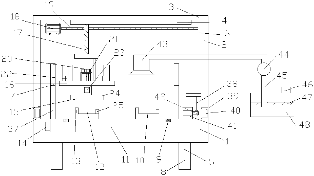
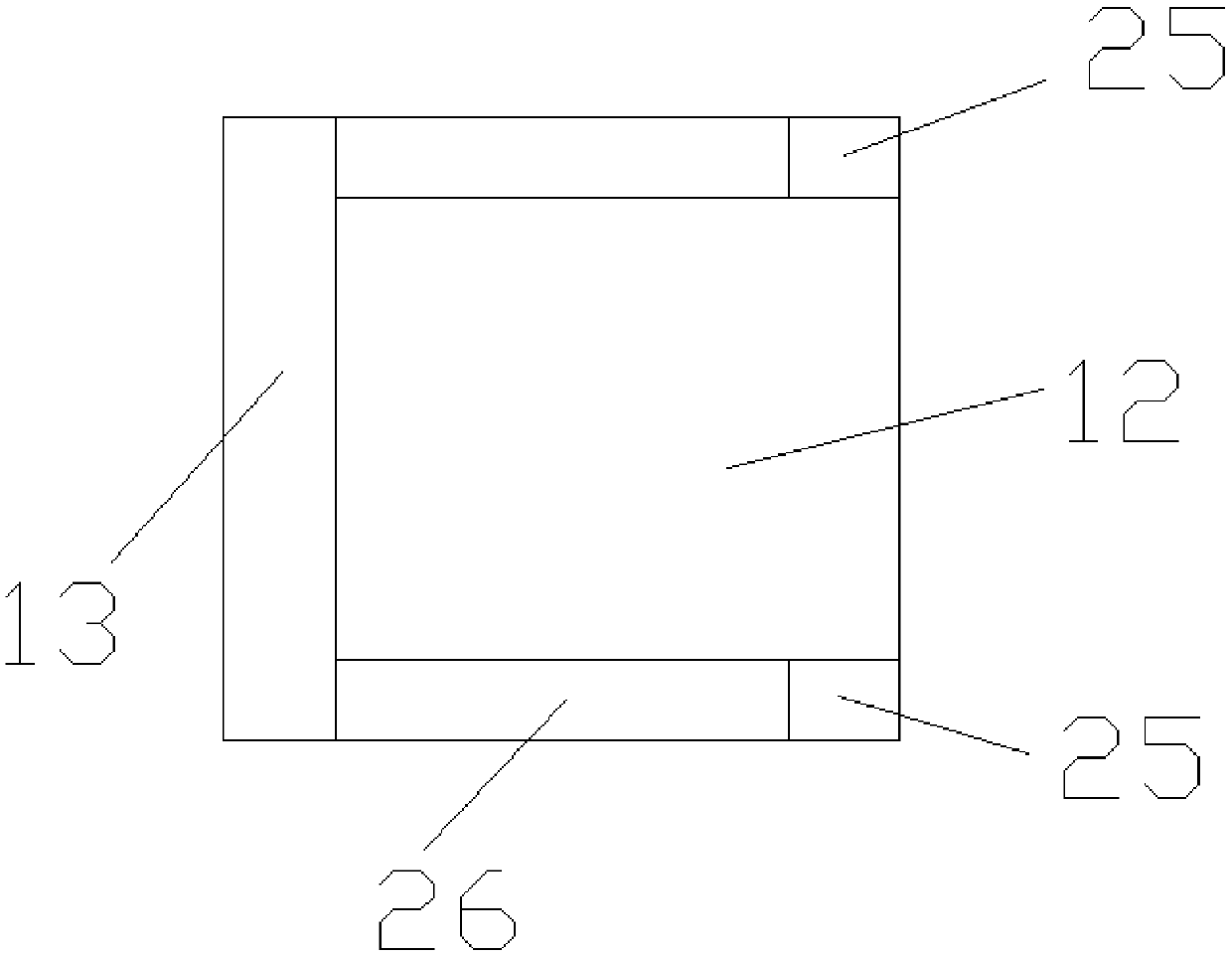
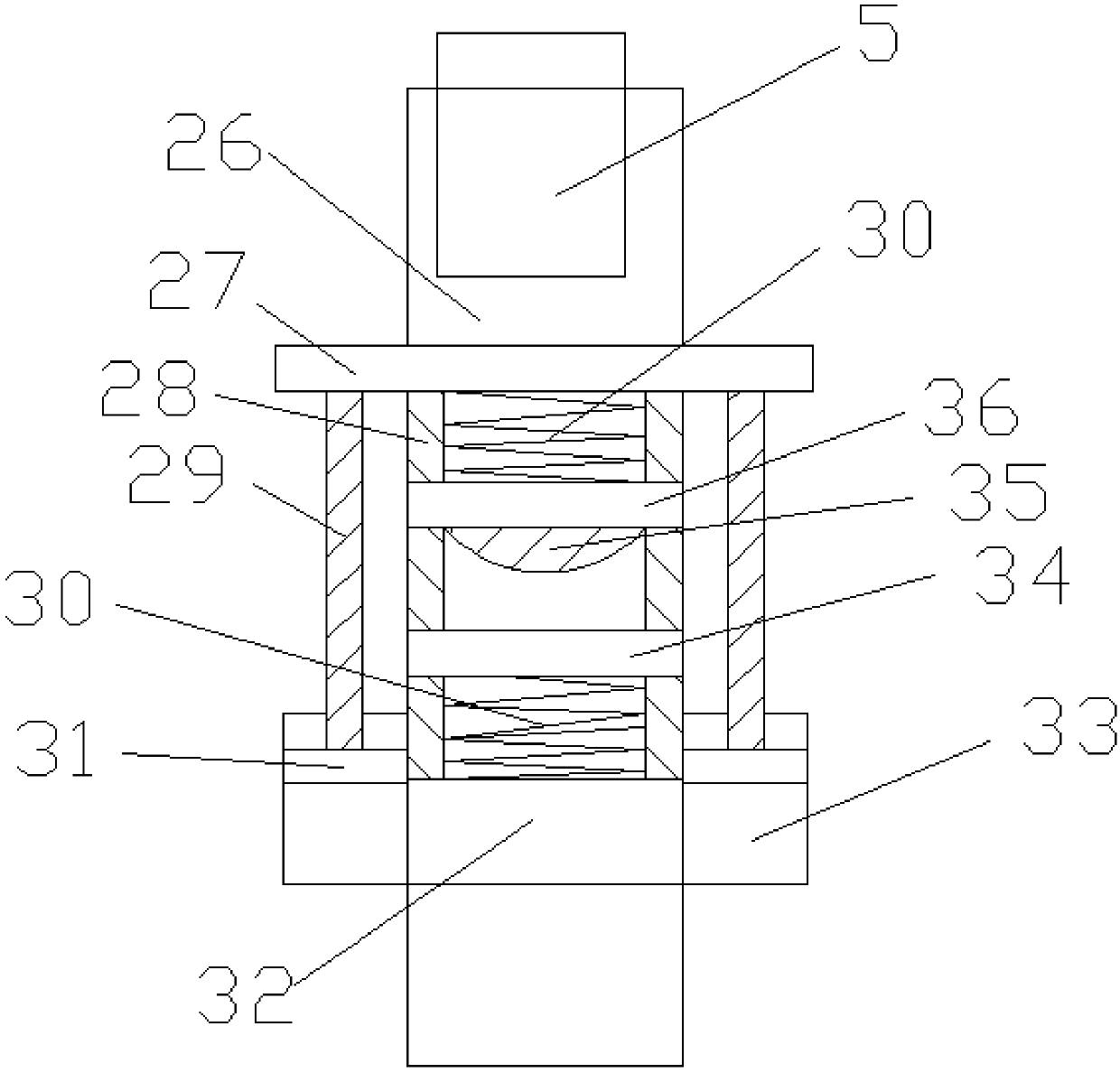
[0019] see Figure 1~3, in an embodiment of the present invention, a hardware pendant surface polishing machine, including a work panel 1 and a support column 5, the upper side of the workbench 1 is provided with a column 2 at the left and right ends, and the lower end of the column 2 is provided with a longitudinal pulley 39 A longitudinal pulley groove 40 is installed on the working panel 1 where the longitudinal pulley 39 is located, and a longitudinal slid...


PUM


Abstract

The invention discloses a hardware hanging part plane polishing machine which comprises a work panel and supporting columns. Stand columns are arranged at the left end and the right end of the upper side of a work table. A sliding rail is mounted on the lower side of a top plate. A sliding plate connected with the sliding rail is mounted on a threaded rod through a threaded hole. The threaded rodand the output end of a horizontal motor are fixedly connected through a connecting device. Air cylinders, a polishing motor and a lifting table are arranged above a fixed plate. The polishing motor is placed on the lifting table. An output shaft of the polishing motor is connected with a rotary disc. A polishing disc is arranged on the lower side of the rotary disc. Multiple clamping devices aremounted on the work panel. A drive device is mounted on one side of a collection cavity. The drive device, the horizontal motor and the polishing motor are connected to a control panel. A shock absorption device is mounted on each supporting column mounted below the work panel. The hardware hanging part plane polishing machine is reasonable in structure and convenient to use; the control panel cancontrol a grinding disc to move up and down and left and right; the polishing efficiency can be improved through the multiple clamping devices; and water spray equipment and the shock absorption devices are arranged, and the equipment service life is prolonged.

Description

technical field [0001] The invention relates to the technical field of hardware pendant processing machinery, in particular to a metal pendant plane polishing machine. Background technique [0002] Plane polishing is one of the most important processes in hardware processing. The most advanced technologies in the polishing machinery industry are concentrated in the United States, Japan and Germany. With the rapid development of polishing technology in these three countries, other countries are more or less affected [0003] certain influence. As far as China is concerned, although the polishing industry has existed for a long time, it has always used foreign machinery and equipment, without its own polishing technology and polishing process. In recent years, with the rapid expansion of market demand, polishing technology is widely used in optics, aviation, automobiles, molds, gemstone processing and various hardware industries. It has a huge market space, and polishing mac...

Claims


Application Information

Patent Timeline
Patent Type & Authority Applications(China)
IPC IPC(8): B24B29/02B24B41/00B24B41/06B24B55/02B24B55/12
CPCB24B29/02B24B41/007B24B41/06B24B55/02B24B55/12
Inventor 杨海斌
Owner WUXI WEI KELAI TECH CO LTD
Why Eureka
Try Eureka