
Yarn reel for spinning

A reel and yarn technology, which is applied in the field of textile yarn reels, can solve the problems of being rolled on top, unable to work with machinery, difficult yarns, etc., and achieves the effect of easy fixing and installation

Inactive Publication Date: 2018-09-07
JIANGSU BEILIN TEXTILE CO LTD
View PDF0 Cites 2 Cited by
  • Summary
  • Abstract
  • Description
  • Claims
  • Application Information

AI Technical Summary

Problems solved by technology

[0002] With the progress of society, textile machinery is becoming more and more advanced. As a textile reel in the textile process, it is an indispensable device in textiles. It has received more and more attention from people. The yarn reel is winding the yarn During the process, due to the different types of yarns, yarn reels of different lengths are required, and the yarn reels are used in conjunction with the spindles. However, the existing yarn reels do not have the function of height adjustment, and the lengths of different spindles are different. Spindles of different lengths need to use yarn reels of different heights, which is very inconvenient to use, and the existing device cannot be fixed to work with the machine when it is placed on the machine, and the outer wall of the existing yarn reel is relatively slippery. It is difficult to roll the yarn on it during work. In addition, the existing devices are not intelligent enough to detect yarn breakage or yarn stagnation, which can easily affect subsequent textile work

Method used

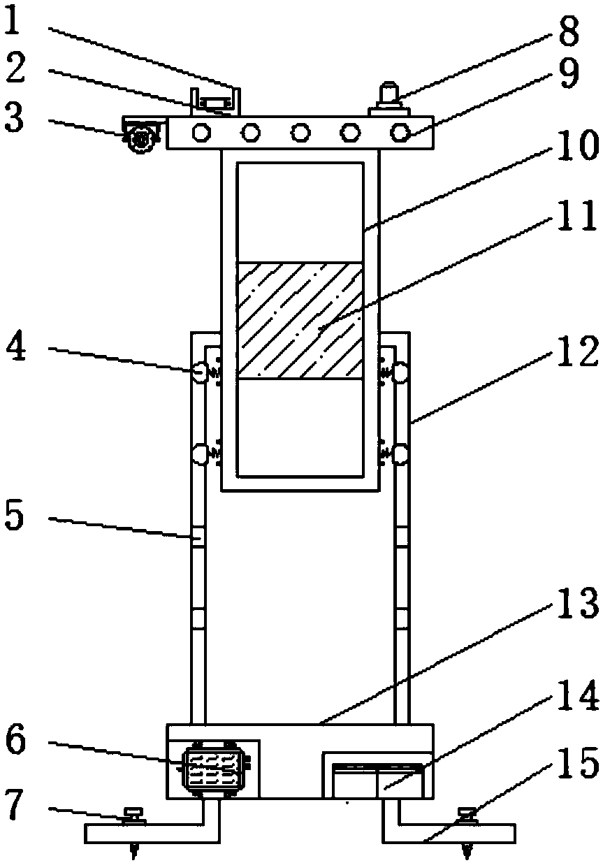
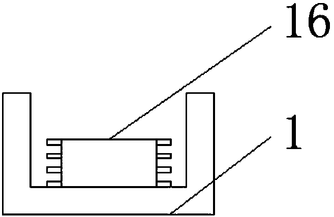
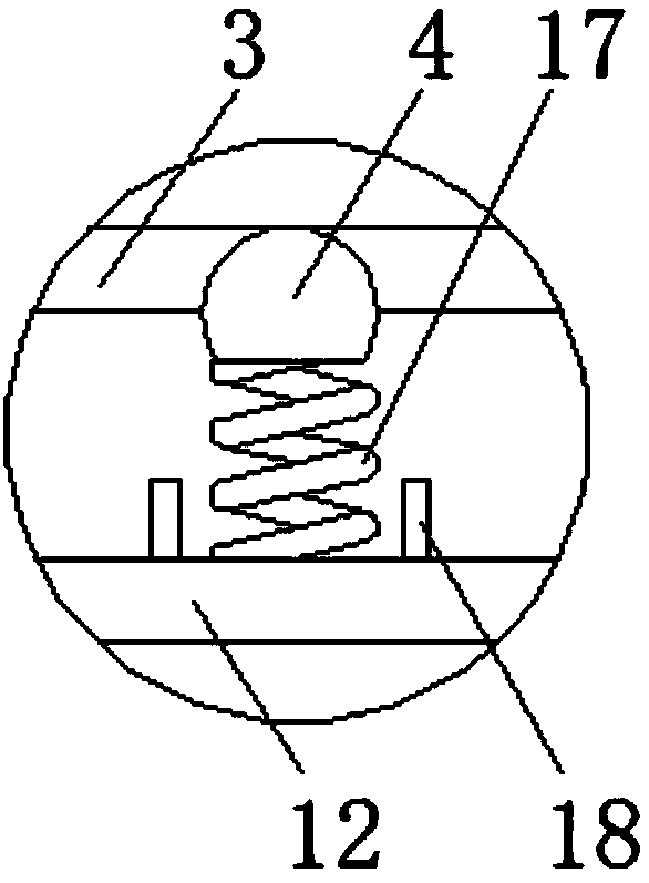

Image

  • Yarn reel for spinning
  • Yarn reel for spinning
  • Yarn reel for spinning

Examples


Embodiment Construction

[0014] The following will clearly and completely describe the technical solutions in the embodiments of the present invention with reference to the accompanying drawings in the embodiments of the present invention. Obviously, the described embodiments are only some, not all, embodiments of the present invention. Based on the embodiments of the present invention, all other embodiments obtained by persons of ordinary skill in the art without making creative efforts belong to the protection scope of the present invention.

[0015] see Figure 1-3 , an embodiment provided by the present invention: a yarn reel for weaving, comprising a first reel 10, a second reel 12 and a base 13, four corners at the bottom of the base 13 are equipped with mounting brackets 15, And the top of mounting frame 15 is all equipped with fixing bolt 7, and one end of base 13 inside is equipped with single-chip microcomputer 6, and the model of single-chip microcomputer 6 can be HT66F017, and the other en...


PUM


Abstract

The invention discloses a yarn reel for spinning. The yarn reel comprises a first reel body, a second reel body and a base. Mounting frames are mounted at the four corners of the bottom end of the base correspondingly, and fixing bolts are mounted at the top ends of the mounting frames correspondingly. A single chip microcomputer is mounted at one end inside the base, and a storage battery is mounted at the other end inside the base. The second reel body is mounted at the top end of the base, and grooves are evenly formed in the side walls of the two sides of the second reel body. The first reel body is mounted in the second reel body, and marbles are mounted on the two sides of the bottom end of the first reel body through springs correspondingly. Check blocks are mounted at the two endsof the springs correspondingly, and a top plate is mounted at the top end of the first reel body. A yarn plate is mounted at one end of the top of the top plate. Through mounting of the marbles, the springs and the grooves, the length of the yarn reel is convenient to adjust, so that the yarn reel is suitable for spindles of different lengths, the length needed for yarn coiling is met, and thus the yarn reel has the practicability.

Description

technical field [0001] The invention relates to the technical field of textile machinery accessories, in particular to a yarn reel for textile use. Background technique [0002] With the progress of society, textile machinery is becoming more and more advanced. As a textile reel in the textile process, it is an indispensable device in textiles. It has received more and more attention from people. The yarn reel is winding the yarn During the process, due to the different types of yarns, yarn reels of different lengths are required, and the yarn reels are used in conjunction with the spindles. However, the existing yarn reels do not have the function of height adjustment, and the lengths of different spindles are different. Spindles of different lengths need to use yarn reels of different heights, which is very inconvenient to use, and the existing device cannot be fixed to work with the machine when it is placed on the machine, and the outer wall of the existing yarn reel is ...

Claims


Application Information

Patent Timeline
IPC IPC(8): B65H75/10B65H75/24B65H75/18
CPCB65H75/10B65H75/18B65H75/241B65H2701/31
Inventor 林城伊
Owner JIANGSU BEILIN TEXTILE CO LTD
Learn More