
Frame splicing method based on cross sectional materials

A technology of cross-shaped and cross-shaped profiles, which is applied in the direction of thin plate connection, connection components, mechanical equipment, etc., can solve the problems of poor connection strength, low splicing efficiency, and difficult splicing, so as to reduce the difficulty of lapping and improve the reliability of impact resistance , the effect of increasing the connection strength

Inactive Publication Date: 2018-09-07
香港新方舟科技有限公司
View PDF10 Cites 1 Cited by
  • Summary
  • Abstract
  • Description
  • Claims
  • Application Information

AI Technical Summary

Problems solved by technology

[0003] The purpose of the present invention is to provide a frame splicing method based on cross profiles in order to solve the shortcomings of poor connection strength, low splicing efficiency, and high splicing difficulty in traditional frame splicing structures.

Method used


Image

  • Frame splicing method based on cross sectional materials
  • Frame splicing method based on cross sectional materials
  • Frame splicing method based on cross sectional materials

Examples


Embodiment

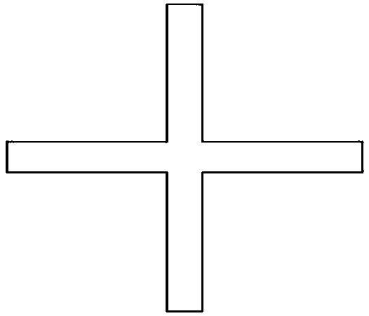
[0017] A kind of frame splicing method based on the cross profile of the present invention, such as figure 1 As shown, the base piece used in this splicing method is a long metal cross section with a cross-shaped cross section, and at least one end of the cross section has a positioning gap inward along a group of parallel sides;

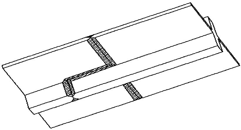
[0018] When the two cross profiles are overlapped end to end, the two cross profiles have a positioning gap and one end is mortise and tenon butt joint and welded, and the two cross profile mortise and tenon joints are processed with welding grooves, such as figure 2 shown;

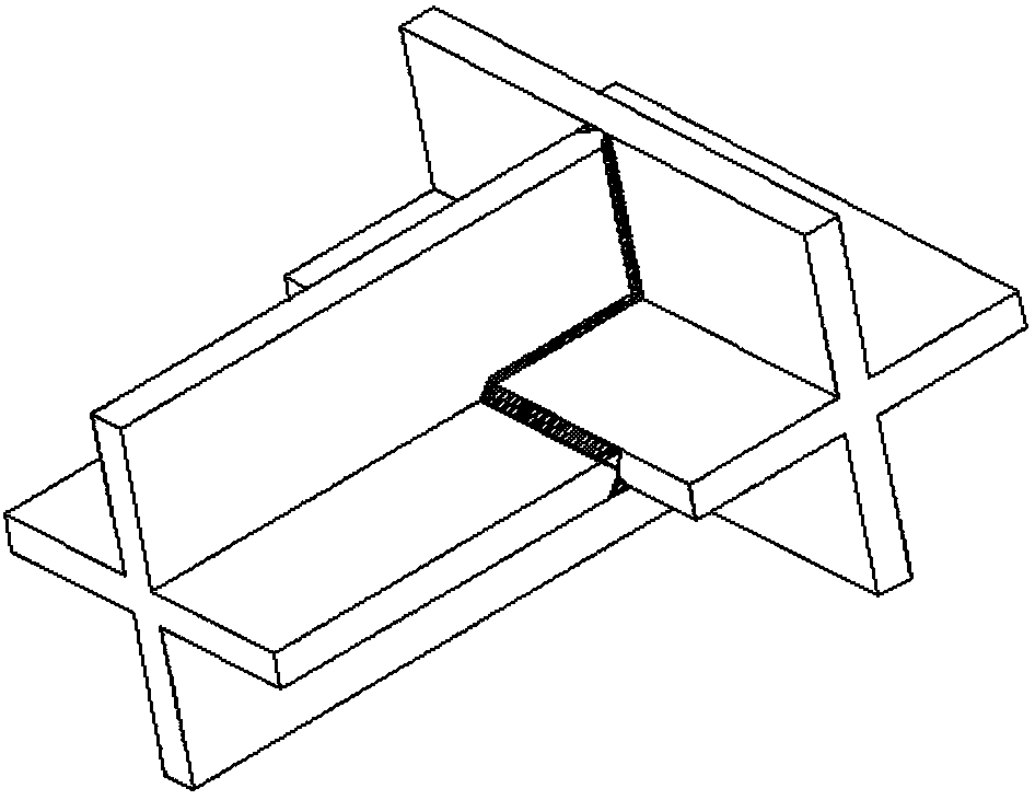
[0019] When the two cross profiles intersect and overlap, one end of the left cross profile with a positioning gap is mortised and tenon-jointed with the side of the right cross profile and fixed by welding, and the inner side of the left cross profile positioning gap is processed as a straight line parallel to the end surface of the cross profile edge, and the mortise and te...


PUM


Abstract

The invention relates to a frame splicing method based on cross sectional materials, and belongs to the field of frame splicing. According to the frame splicing method, the adopted basic parts are thelong-strip-shaped metal cross sectional materials with cross sections, a locating notch is inwards formed in at least one end of each cross sectional material along a group of parallel borders; whentwo cross sectional materials are in lapping end to end, the ends, with the formed locating notches, of the two cross sectional materials are in mortise and tenon butt joint and are fixed in a weldingmanner; and when two cross sectional materials are in intersection lapping, the end, with the formed locating notch, of one cross sectional material is in mortise and tenon butt joint with and fixedly welded to the side edge of the other cross sectional material, and all the cross sectional materials are in lapping end to end or arranged in an intersection lapping manner to form a needed frame structure. According to the frame splicing method, the adopted cross sectional materials are welded to be fixed after being subjected to butt joint through mortise and tenon structures, the connection strength of lapping positions is greatly improved, the reliability of shock resistance of a frame after butt joint is carried out is improved, the difficulty of lapping is reduced, and the accuracy oflapping is guaranteed.

Description

technical field [0001] The invention relates to a frame splicing method based on a cross profile, belonging to the field of frame splicing. Background technique [0002] When splicing some large-scale frame structures, angle steel or I-shaped steel is usually used as the basic parts. The lap joints between the basic parts are welded or bolted. The welding strength of the weld and the fracture strength of the bolt are taken as The overlapping of the basic parts will become the weak point of the entire support structure. Under a large impact overload, the welds or bolted joints of the basic parts may be prematurely broken. In addition, when the two base parts in the support frame are required to be connected vertically or even at a fixed angle, it is difficult to fix the angle when welding or bolting is used, and it will cost a lot to control the error during the splicing process. time, reducing productivity. Contents of the invention [0003] The purpose of the present in...

Claims


Application Information

Patent Timeline
IPC IPC(8): F16B5/08
Inventor 丁华山
Owner 香港新方舟科技有限公司
Learn More