

Wear resistance testing equipment for wheel rubber for automobiles
A technology of wear resistance and testing equipment, which is applied in the direction of testing wear resistance, measuring devices, strength characteristics, etc., can solve the problems of people around, inflexible hands, easy to be injured by tools, etc., and achieve the effect of avoiding injuries
- Summary
- Abstract
- Description
- Claims
- Application Information
AI Technical Summary
Problems solved by technology
Method used
Image

Examples
Embodiment 1
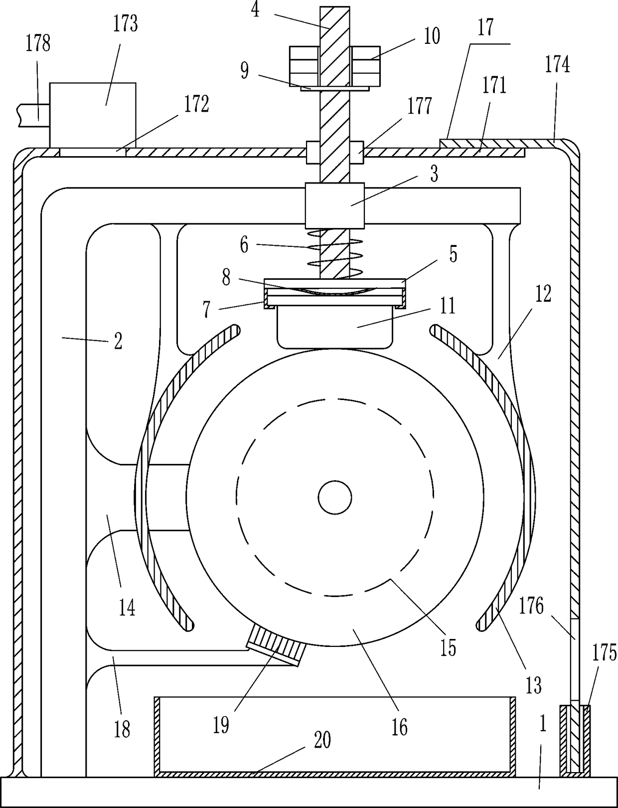
[0016] A kind of equipment for testing the wear resistance of automobile wheel rubber, such as figure 1 As shown, it includes a base plate 1, a 7-shaped rod 2, a guide sleeve 3, a guide rod 4, a horizontal plate 5, a first spring 6, an L-shaped plate 7, an elastic sheet 8, a fixed plate 9, a weight 10, and a vertical rod 12 , arc baffle plate 13, cross bar 14, driving motor 15 and grinding wheel 16, base plate 1 top left side is equipped with 7 type bar 2, and 7 type bar 2 inner left side middle part is equipped with cross bar 14, and cross bar 14 right ends A drive motor 15 is installed, and the output shaft of the drive motor 15 is connected with a grinding wheel 16 by a coupling, and vertical rods 12 are installed on the left and right sides of the top, left and right sides of the 7-type rod 2, and arcs are installed on the left and right sides of the vertical rods 12 bottom ends. Shaped baffle plate 13, arc-shaped baffle plate 13 is positioned at grinding wheel 16 left and...
Embodiment 2
[0018] A kind of equipment for testing the wear resistance of automobile wheel rubber, such as figure 1 As shown, it includes a base plate 1, a 7-shaped rod 2, a guide sleeve 3, a guide rod 4, a horizontal plate 5, a first spring 6, an L-shaped plate 7, an elastic sheet 8, a fixed plate 9, a weight 10, and a vertical rod 12 , arc baffle plate 13, cross bar 14, driving motor 15 and grinding wheel 16, base plate 1 top left side is equipped with 7 type bar 2, and 7 type bar 2 inner left side middle part is equipped with cross bar 14, and cross bar 14 right ends A drive motor 15 is installed, and the output shaft of the drive motor 15 is connected with a grinding wheel 16 by a coupling, and vertical rods 12 are installed on the left and right sides of the top, left and right sides of the 7-type rod 2, and arcs are installed on the left and right sides of the vertical rods 12 bottom ends. Shaped baffle plate 13, arc-shaped baffle plate 13 is positioned at grinding wheel 16 left and...
Embodiment 3
[0021] A kind of equipment for testing the wear resistance of automobile wheel rubber, such as figure 1 As shown, it includes a base plate 1, a 7-shaped rod 2, a guide sleeve 3, a guide rod 4, a horizontal plate 5, a first spring 6, an L-shaped plate 7, an elastic sheet 8, a fixed plate 9, a weight 10, and a vertical rod 12 , arc baffle plate 13, cross bar 14, driving motor 15 and grinding wheel 16, base plate 1 top left side is equipped with 7 type bar 2, and 7 type bar 2 inner left side middle part is equipped with cross bar 14, and cross bar 14 right ends A drive motor 15 is installed, and the output shaft of the drive motor 15 is connected with a grinding wheel 16 by a coupling, and vertical rods 12 are installed on the left and right sides of the top, left and right sides of the 7-type rod 2, and arcs are installed on the left and right sides of the vertical rods 12 bottom ends. Shaped baffle plate 13, arc-shaped baffle plate 13 is positioned at grinding wheel 16 left and...
PUM
 Abstract
Description
Claims
Application Information