

Improved frame type bee feeder
A feeder and frame-type technology, which is applied in beekeeping, application, animal husbandry, etc., can solve the problems of drowning in water or honey, inconvenient entry and exit, etc., and achieve easy handling, reduced labor, and easy access Effect
- Summary
- Abstract
- Description
- Claims
- Application Information
AI Technical Summary
Problems solved by technology
Method used
Image

Examples
Embodiment 1
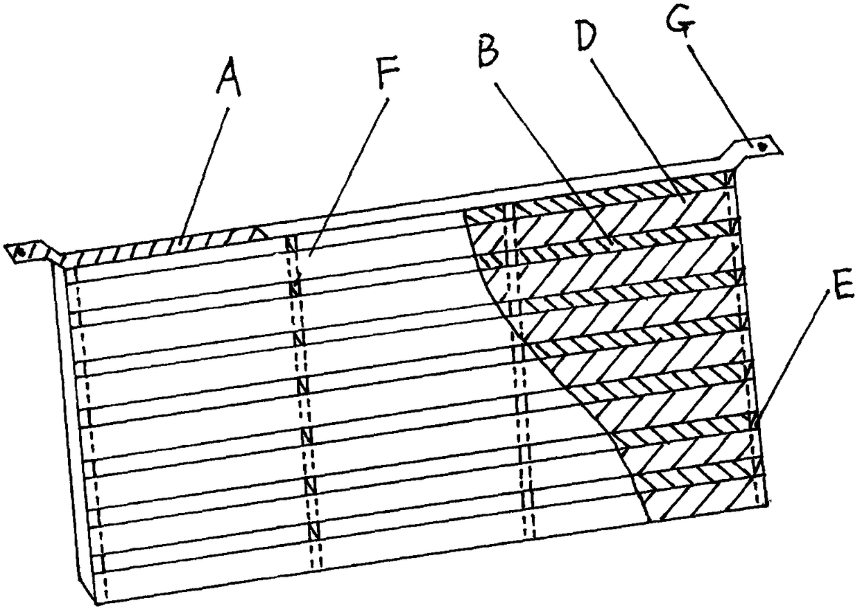
[0023] Example 1: Combination figure 1 , figure 2 To further explain the present invention
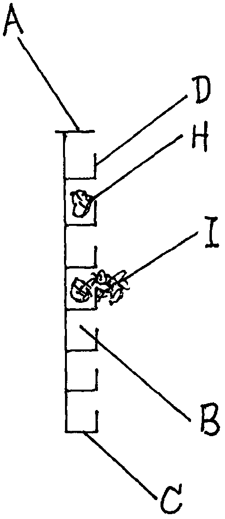
[0024] by figure 1 , figure 2 It can be seen that there are 7 elongated grooves B transversely provided on the outer surface of the frame feeder A, and the edge of the groove edge C at the lower part of each groove has an upwardly protruding lip D along the lip Relative to the groove edge at the lower part of each groove, it protrudes upward at a right angle. Both ends of the 7 grooves are blocked by the frame plate E. In order to be firm, the middle part of the groove area (herein referred to as the pollen groove) is provided with a reinforcing plate F connecting the sides of each groove. Two frame ears G are also provided on the frame feeder. When in use, fill the pollen feed H into each groove, because the lip along the edge of the groove at the lower part of each groove prevents the pollen feed from contacting the air, effectively preventing the evaporation of water in the pollen ...
Embodiment 2
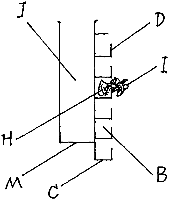
[0026] Example 2: Combination image 3 , Figure 4 To further explain the present invention
[0027] by image 3 , Figure 4 It can be seen that a honey trough J and a water trough K with an upper open trough structure are added to the other side of the frame feeder structured as described in Example 1, and the two troughs are arranged side by side in two horizontally. Between the frame ears G, it is separated by the clip wall L. The bottom plate M of the honey trough J and the bottom plate of the water trough K are on the same plane. So far, the frame feeder has a trough that can separately hold three foods: water, honey and pollen feed. In this way, not only the pollen feed H contained on the feeder can be kept moist for a long time, but also the feeder can simultaneously feed the bees with pollen feed, water and honey.
Embodiment 3
[0029] Example 3: Combination Figure 5 , Image 6 To further explain the present invention
[0030] by Figure 5 , Image 6 It can be seen that the water tank K and the honey tank J are arranged up and down and constitute the main part of the frame feeder. The honey trough J is an upper open trough structure and is arranged on the upper part of the feeder. The water tank K is arranged at the lower part of the feeder and has a shallow tank structure. The bottom plate M of the honey trough J is horizontally arranged in the middle of the feeder. A water storage tank O is provided between the bottom plate M of the honey tank J and the water tank K. There is a water injection port P on the water storage bin O. There is a filter Q at the bottom of the water injection port P. A drainage tube R is provided on the bottom plate N of the water storage silo O, and the water in the water storage silo O can be controlled to flow into the water tank K through a water flow controller S with...
PUM
 Abstract
Description
Claims
Application Information