
Optical waveguide structure and optical system

An optical system and optical waveguide technology, applied in the field of optical waveguides, can solve problems such as hindering development, affecting imaging quality, and making holographic gratings difficult

Inactive Publication Date: 2018-09-11
SHENZHEN ROYOLE TECH CO LTD
View PDF8 Cites 4 Cited by
  • Summary
  • Abstract
  • Description
  • Claims
  • Application Information

AI Technical Summary

Problems solved by technology

Holographic waveguide uses holographic technology and optical waveguide concept to realize display, but the light energy utilization rate of the system is low, the preparation of holographic grating is difficult, and the stray light and dispersion introduced by diffraction seriously hinder its development.
The semi-permeable film array waveguide uses the principle of geometric optics catadioptric reflection to realize the display. The dispersion is small and it is easy to realize the color display. Therefore, the design and production requirements are far lower than the holographic waveguide display, but the traditional semi-permeable film array waveguide causes serious ghost images. Affect image quality

Method used


Image

  • Optical waveguide structure and optical system
  • Optical waveguide structure and optical system
  • Optical waveguide structure and optical system

Examples


Embodiment Construction

[0022] In order to enable those skilled in the art to better understand the solutions of the present invention, the following will clearly and completely describe the technical solutions in the embodiments of the present invention in conjunction with the drawings in the embodiments of the present invention. Obviously, the described embodiments are only It is an embodiment of a part of the present invention, but not all embodiments. Based on the embodiments of the present invention, all other embodiments obtained by persons of ordinary skill in the art without making creative efforts shall fall within the protection scope of the present invention.

[0023] Each will be described in detail below.

[0024] The terms "first", "second", "third" and "fourth" in the description and claims of the present invention and the drawings are used to distinguish different objects, rather than to describe a specific order .

[0025] See figure 1 , figure 1 It is a schematic diagram of an o...


PUM


Abstract

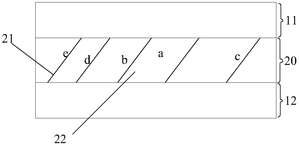
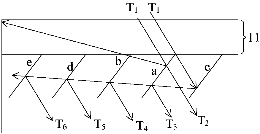
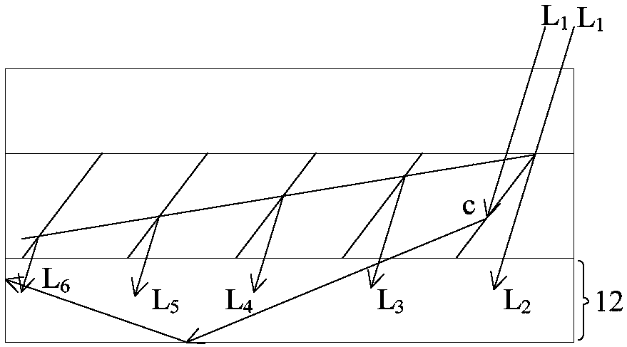
An optical waveguide structure (301) comprises at least one first substrate (11) and an expansion wave guidance (20), the first substrate (11) is connected with the expansion wave guidance (20), the expansion wave guidance (20) comprises a plurality of semipermeable membranes (a, b, c, d, e) mutually obliquely laid into the substrate (22) in parallel, the at least one side of the left and right sides of the optical waveguide (301) is provided with light absorption materials, wherein incident light (L1, L2) enter the expansion wave guidance (20) and then emits a plurality of emitting light (L2,L3, L4, L5, L6, T2, T3, T4, T5, T6) being mutually in parallel; when the incident light (L1, L2) enters the expansion wave guidance (20) and is reflected by at least one of the semipermeable membranes (a, b, c, d, e), the reflection light enters the first substrate (11), and then is subjected to total reflection spreading through the first substrate (11) to the side, provided with the light absorption materials, of the optical wave guidance (301), or the incident light (L1, L2) enters the expansion wave guidance (20) and is reflected by at least one of the semipermeable membranes (a, b, c, d,e), the reflection light spreads to the side provided with the light absorption materials of the optical wave guidance (301) through the first substrate (11). The optical system comprising the optical wave guidance (301) can reduce the ghost image so as to improve the imaging quality.

Description

technical field [0001] The invention relates to the field of optical waveguides, in particular to an optical waveguide structure and an optical system. Background technique [0002] Head-Mounted Display (HMD) has been widely used in military, industrial, medical and other fields due to its immersion, interactivity and ability to improve situational awareness. With the increasing maturity of microdisplay technology, optical processing technology and optical design theory, HMD is developing towards miniaturization. [0003] In view of the special requirements for wearing on the head, the existing penetrating HMD usually adopts a combination of a foldback relay structure and an off-axis reflection combination mirror. Although the foldback relay structure enables the HMD to obtain a large exit pupil, the use of off-axis reflective combination mirrors greatly increases the difficulty of system off-axis aberration correction. It can be seen that the combination of the combined m...

Claims


Application Information

Patent Timeline
Patent Type & Authority Applications(China)
IPC IPC(8): G02B27/01
CPCG02B27/0172G02B17/00G02B27/01
Inventor 李国洲
Owner SHENZHEN ROYOLE TECH CO LTD
Learn More