Lamp display device

A technology for display devices and lamps, which is applied to household appliances, display stands, display hangers, etc., can solve the problems of inconvenient installation and movement, movement of lamps, and single shape of display racks, and achieves the effect of being easy to place, move and use.

Pending Publication Date: 2018-09-14
ZHONGSHAN E MAIL LIGHTING CO LTD
View PDF0 Cites 0 Cited by
  • Summary
  • Abstract
  • Description
  • Claims
  • Application Information

AI Technical Summary

Problems solved by technology

It is common to install a display stand in the exhibition hall and place the lamps on the display stand. The shape of the display stand is rel

Method used


Image

  • Lamp display device
  • Lamp display device
  • Lamp display device

Examples


Example Embodiment

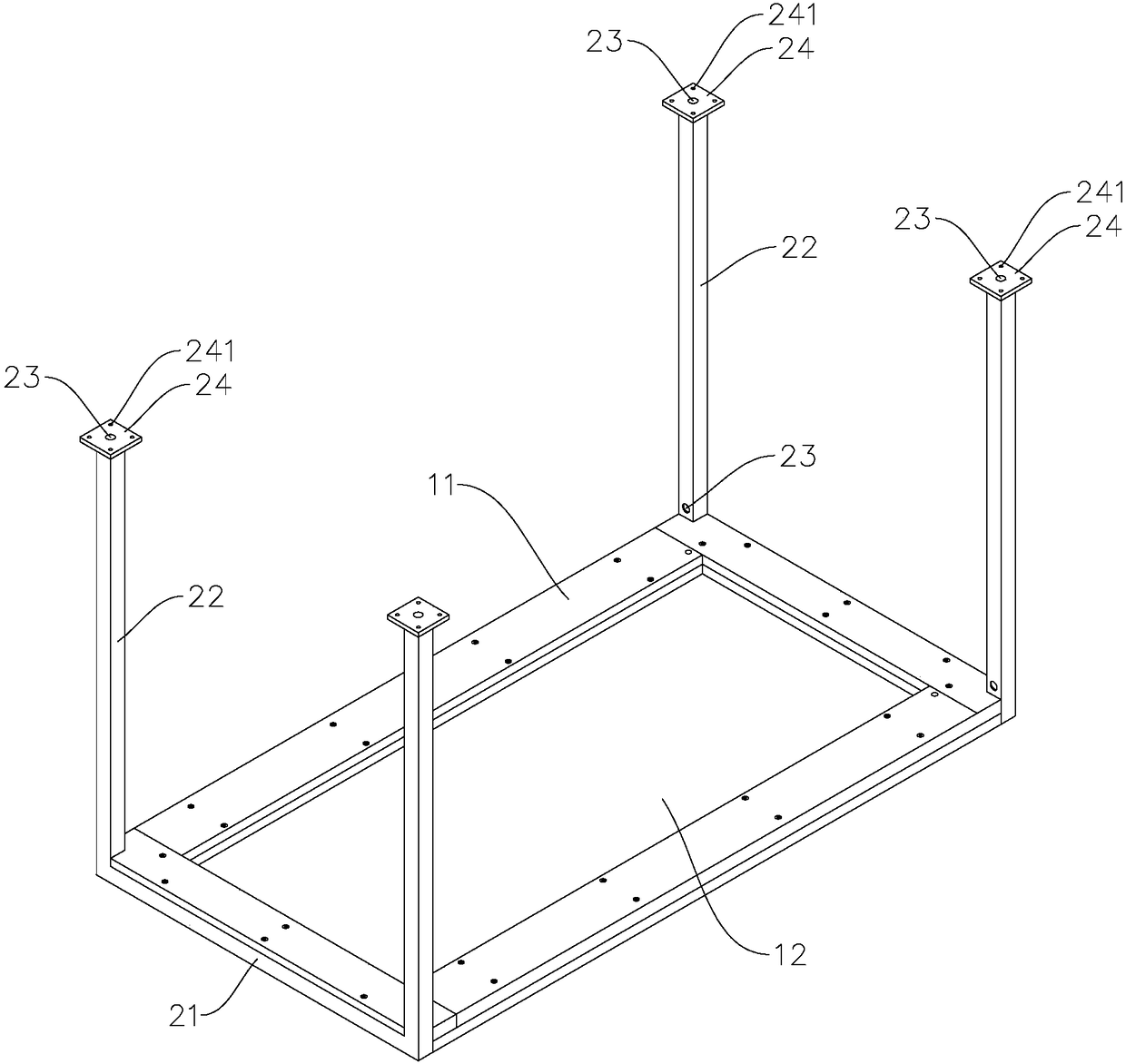
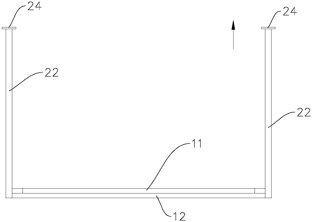
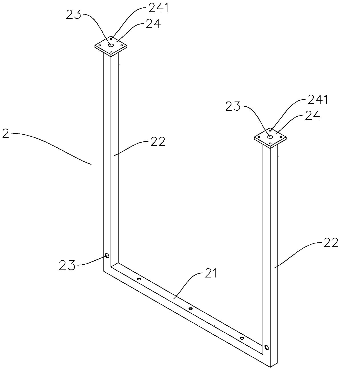
[0023] refer to Figure 1 to Figure 6 (In this paper, the direction indicated by the arrow 2 in the figure is the upward direction), the present invention is a lamp display device, which includes a board 1, and mounting holes for installing lamps are provided on the bottom of the board 1 .

[0024] Specifically, the installation holes include one or more of the lamp socket hole 121 , the lamp groove 122 and the wiring hole 123 . The lamp holder hole 121 can be used for installing lamps such as downlights and ceiling lamps, the lamp groove 122 can be used for installing lamps such as strip lights, and the wiring hole 123 can be used for installing wires of lamps such as ceiling lamps, pendant lamps and spotlights. Of course, the above-mentioned lamps and installation holes are only some installation examples. In practical applications, installation holes of different shapes or sizes can also be set according to the needs of different lamps, and other types of lamps can also be ...


PUM


Abstract

The invention discloses a lamp display device, comprising a plate. The bottom of the plate is provided with mounting holes for the mounting of lamps; the mounting holes are used to mount lamps such that the lamps are arranged neatly; the lamps can be avoided being moved by external force. In addition, the plate is easy to place and move such that the lamp display device is easy for a user to use.

Description

technical field [0001] The invention relates to a lamp display device. Background technique [0002] For lamp manufacturers and distributors, many different types of lamps need to be displayed. It is common to install display racks in the exhibition hall and place lamps on the display racks. The shape of the display racks is relatively simple, and it is inconvenient to install and move. The lamps placed on the display racks are also prone to movement due to external forces. Therefore, there is a need for a device for displaying lamps, which is easy to place and move, and can also play a good role in positioning the lamps and is convenient for users to use. Contents of the invention [0003] In order to solve the above problems, the present invention provides a lamp display device that is convenient to use. [0004] The technical solution adopted by the present invention to solve its technical problems is: [0005] The lamp display device includes a board, and the bottom...

Claims


Application Information

Patent Timeline
IPC IPC(8): A47F7/00A47F5/00A47F5/10
CPCA47F7/00A47F5/00A47F5/10A47F2007/0085
Inventor 蒲江
Owner ZHONGSHAN E MAIL LIGHTING CO LTD
Why Eureka
Try Eureka