Automatic polishing mechanism for connecting holes in end parts of hardware tool connecting rod

A technology of end connection and grinding mechanism, which is applied to machine tools, manufacturing tools, and metal processing equipment designed for grinding the rotating surface of workpieces. It can solve problems such as low efficiency, heavy manual labor, and manual grinding, and achieve high efficiency. , good effect

Inactive Publication Date: 2018-09-14
FOSHAN XUNAOJIE AUTOMATION TECH CO LTD
View PDF5 Cites 2 Cited by
  • Summary
  • Abstract
  • Description
  • Claims
  • Application Information

AI Technical Summary

Problems solved by technology

[0002] In the existing hardware tools, the connecting rod is a commonly used part. It is generally formed with a rectangular block at one end of the rod, a square hole is formed at the end of the rectangular block, and a cylindrical hole is formed at the other end of the rod. The square hole and the Cylindrical holes can be connected with different connectors, but in processing, the square holes and cylindrical holes need to be manually polished after forming, which is inefficient and labor-intensive

Method used


Image

  • Automatic polishing mechanism for connecting holes in end parts of hardware tool connecting rod
  • Automatic polishing mechanism for connecting holes in end parts of hardware tool connecting rod

Examples


Embodiment

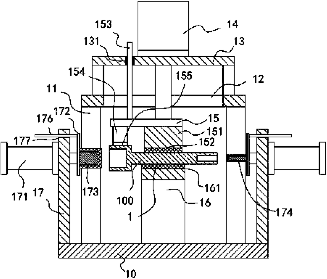
[0018] Example: see Figure 1 to Figure 2 As shown, an automatic grinding mechanism for the end connection hole of a hardware tool post includes a main base plate 10, an upper support frame 11 is fixed in the middle of the top surface of the main base plate 10, and the middle part of the top plate of the upper support frame 11 is formed with a long shaped through groove 12, the top surface of the top plate of the upper support frame 11 is fixed with an upper pneumatic support frame 13, and the top surface of the top plate of the upper pneumatic support frame 13 is fixed with a compression cylinder 14, and the push rod of the compression cylinder 14 passes through the upper pneumatic support frame. The top plate of support frame 13 is also fixed with lifting plate 15, and the push rod of pressing cylinder 14 is inserted and sleeved in elongated through groove 12, and the bottom surface of lifting plate 15 is fixed with upper pressing block 151, and the bottom surface of upper pr...


PUM


Abstract

The invention discloses an automatic polishing mechanism for connecting holes in end parts of a hardware tool connecting rod. The automatic polishing mechanism comprises a main bottom plate, wherein an upper support frame is fixed in the middle of the top surface of the main bottom plate; a long through groove is formed in the middle of a top plate of the upper support frame; an upper pneumatic support frame is fixed on the top surface of the top plate of the upper support frame; a pressing cylinder is fixed on the top surface of a top plate of the upper pneumatic support frame; a push rod ofthe pressing cylinder penetrates the top plate of the upper pneumatic support frame, fixedly equipped with a lifting plate and inserted into the long through groove in a sleeving manner; an upper pressing block is fixed on the bottom surface of the lifting plate; an upper arc groove is formed in the bottom surface of the upper pressing block; a lower support frame is fixed on the top surface of the middle of the main bottom plate; a lower arc groove is formed in the middle of the top surface of a top plate of the lower support frame; and rod parts of a to-be-machined connecting rod are inserted into the upper arc groove and the lower arc groove in a sleeving manner. The automatic polishing mechanism can clamp the to-be-machined connecting rod automatically and polish the inner side walls of a square hole and a cylindrical hole of the connecting rod automatically, is high in efficiency and has good effect.

Description

Technical field: [0001] The invention relates to the technical field of hardware processing equipment, and more specifically relates to an automatic grinding mechanism for connecting holes at the ends of hardware tools. Background technique: [0002] In the existing hardware tools, the connecting rod is a commonly used part. It is generally formed with a rectangular block at one end of the rod, a square hole is formed at the end of the rectangular block, and a cylindrical hole is formed at the other end of the rod. The square hole and the Cylindrical holes can be connected with different connectors, but during processing, both the square holes and cylindrical holes need to be manually polished after forming, which is inefficient and labor-intensive. Invention content: [0003] The purpose of the present invention is to address the deficiencies of the prior art, and to provide an automatic grinding mechanism for the end connecting hole of a hardware tool connecting rod, whi...

Claims


Application Information

Patent Timeline
IPC IPC(8): B24B5/48B24B19/00B24B41/06
CPCB24B5/48B24B19/00B24B41/06
Inventor 叶小桥
Owner FOSHAN XUNAOJIE AUTOMATION TECH CO LTD
Why Eureka
Try Eureka