Uniform displacement mechanism

A displacement mechanism and uniform technology, applied in the direction of manipulators, program-controlled manipulators, manufacturing tools, etc., can solve the problem of high equipment cost and achieve the effect of low equipment cost

Active Publication Date: 2018-09-14
昆山奥泰克自动化科技有限公司
View PDF11 Cites 3 Cited by
  • Summary
  • Abstract
  • Description
  • Claims
  • Application Information

AI Technical Summary

Problems solved by technology

[0002] Various complex movement requirements are involved in the automation mechanism. Sometimes a row of mechanisms needs to maintain a uniform distance during the work process, that is, the distance between adjacent mechanisms can change over time, but at a certain moment between adjacent mechanisms The spacing between them is always equal to each other. According to the existing means, each mechanism is generally equipped with a mechanical arm, and these mechanical arms are connected through data, so that the spacing can be controlled evenly in real time, but the cost of equipment is relatively high.

Method used


Image

  • Uniform displacement mechanism
  • Uniform displacement mechanism
  • Uniform displacement mechanism

Examples


Embodiment Construction

[0033] Below in conjunction with specific embodiment, content of the present invention is described in further detail:

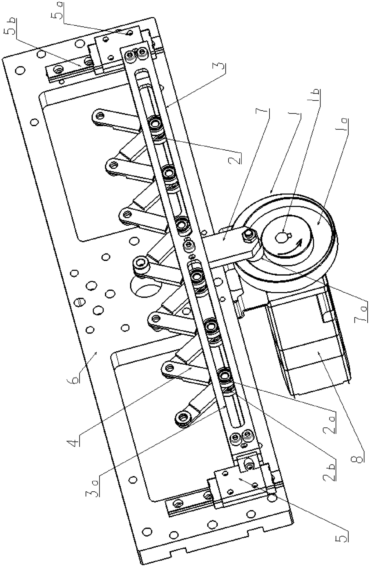
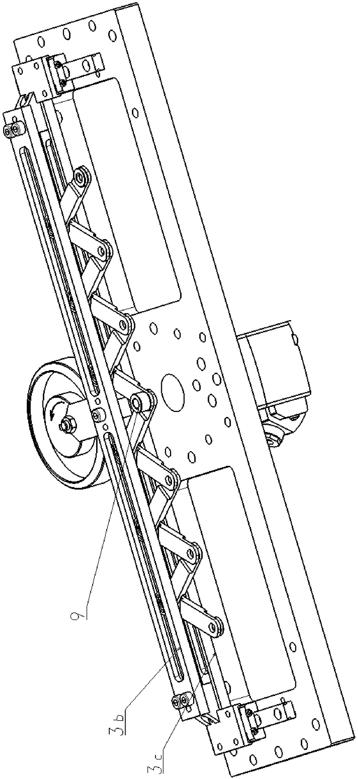
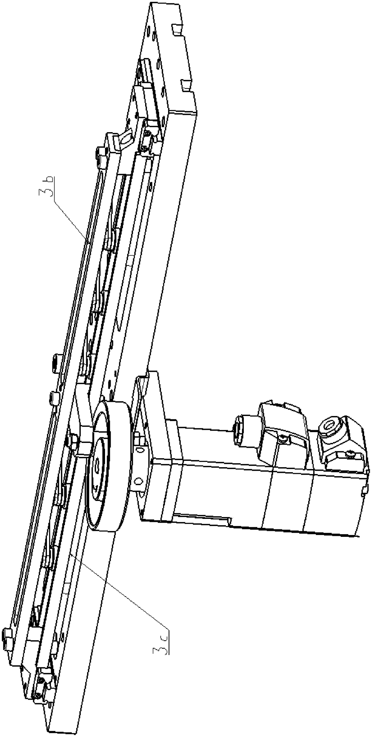
[0034] In order to achieve the purpose of the present invention, a uniform displacement mechanism includes: a cam 1, an annular groove 1a is provided on a circular end surface of the cam 1, and the center of the annular groove 1a does not coincide with the rotating shaft 1b of the cam 1; a push-pull plate 3. The extension arm 7 is connected to the annular groove 1a. With the rotation of the cam 1, the push-pull plate 3 performs linear reciprocating motion. The push-pull plate 3 is equipped with a waist-shaped groove 3a extending along its own direction; the telescopic arm is composed of several connecting rods 4 It is composed of a Z-shaped hinge, the hinge of the connecting rod 4 coincides with two parallel spatial straight lines, and each hinge on one of the spatial straight lines is equipped with a pulley block 2, and the pulley block 2 is assembled with t...


PUM


Abstract

The invention discloses a uniform displacement mechanism. The uniform displacement mechanism comprises a cam, a push-pull plate and a stretchable arm, wherein an annular groove is formed in a circle end surface of the cam, and the circle center of the annular groove does not coincide with a rotating shaft of the cam; the push-pull plate is connected with the annular groove through an extending armto perform linear reciprocating motion along with the rotation of the cam, and waist-shaped grooves extending in the direction of the waist-shaped groove are formed in the push-pull plate; the stretchable arm comprises a plurality of connecting rods which are in a Z-shaped hinge joint, and the hinged positions of the connecting rods coincide with two mutually parallel spatial straight lines, wherein each hinge joint of one of the spatial straight lines is provided with a pulley block, the pulley blocks are assembled with the waist-shaped grooves, and the pulley blocks are provided with rolling degree of freedom in the waist-shaped grooves; and a fixed hinge joint is arranged in the hinged positions of the other spatial straight line, the pulley blocks roll inside the waist-shaped groovesalong with the linear reciprocating motion of the push-pull plate, the hinge joints on the two spatial straight lines also move along with the two spatial straight lines, and the distance between theadjacent hinge joints is equal in real-time. The uniform displacement mechanism has the advantages that the equipment cost is low, the distance between the position points is variable, but is equal inreal-time.

Description

technical field [0001] The invention relates to the field of non-standard automation, in particular to a uniform displacement mechanism. Background technique [0002] Various complex movement requirements are involved in the automation mechanism. Sometimes a row of mechanisms needs to maintain a uniform distance during the work process, that is, the distance between adjacent mechanisms can change over time, but at a certain moment between adjacent mechanisms The spacing between them is always equal to each other. According to the existing means, each mechanism is generally equipped with a mechanical arm, and these mechanical arms are connected through data, so that the spacing can be controlled evenly in real time, but the equipment cost is relatively high. Contents of the invention [0003] The problem to be solved by the present invention is to provide a uniform displacement mechanism with low equipment cost, and the distance between each position point is variable but e...

Claims


Application Information

Patent Timeline
Patent Type & Authority Applications(China)
IPC IPC(8): B25J9/00
CPCB25J9/00B25J9/0009
Inventor 张焕新徐爱新朱国辉丁晓燕
Owner 昆山奥泰克自动化科技有限公司
Why Eureka
Try Eureka