Dust control device and method

A technology of a dust exhaust pipe and a dust hood is applied in the field of dust control devices, which can solve the problems of high equipment failure rate, environmental pollution, poor working environment, etc., and achieve the effects of reducing environmental pollution, ensuring smooth pipelines, and improving dust removal efficiency.

Pending Publication Date: 2018-09-14
广西科穗环境科技有限公司
View PDF0 Cites 0 Cited by
  • Summary
  • Abstract
  • Description
  • Claims
  • Application Information

AI Technical Summary

Problems solved by technology

[0005] The purpose of the present invention is to provide a dust control device and method, so as to overcome the existing environmental pollution and equipment failure rate that are easily caused by dust extraction devices in places where bulk materials are transported by means of wind and air. And the disadvantage of poor working environment

Method used


Image

  • Dust control device and method

Examples


Embodiment 1

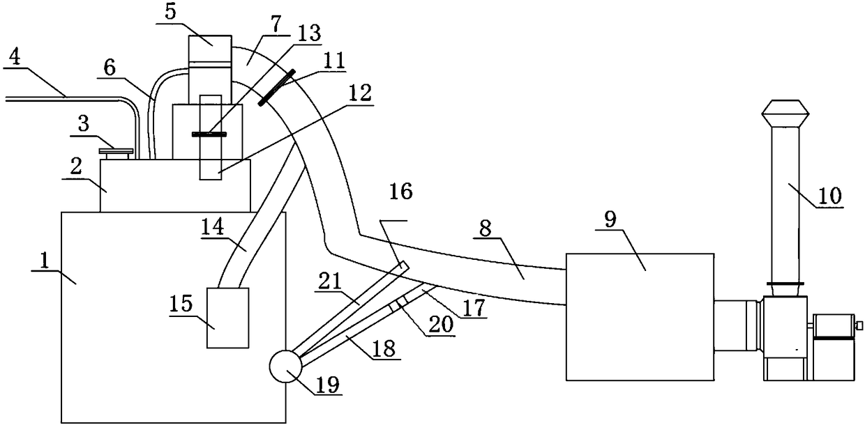
[0026] figure 1 Shows a schematic structural view of a dust control device according to a preferred embodiment of the present invention, the dust control device includes a storage box 2, a first dust control device 5, a second dust control device 9 and a dust collection hood 15, refer to figure 1 , The material storage box 2 is arranged in the material use place 1, and its inner cavity is closed. The storage box 2 is connected with the feeding pipe 4 for receiving and storing materials. The feed pipe 4 uses compressed air as a power source to transport the material into the storage box 2. When the material enters the storage box 2, it will generate relatively large dust under the impact of the air pressure. When the present invention is applied to the chiller, the material use place 1 is the chiller, the material storage box 2 is the sand storage box arranged on the chiller, and the feeding pipe 4 uses compressed air as a power source to transport the casting sand In the san...

Embodiment 2

[0033] The present invention also provides a fugitive dust control method, which adopts the above-mentioned dust control device, and when the feeding pipe 4 transports the material into the storage box 2, the dust generated in the storage box 2 passes through the first air inlet along with the airflow. The pipe 6 enters the first dust control device 5 for processing, and then the air flow passes through the first air outlet pipe 7 and the second air inlet pipe 8 and enters the second dust control device 9 for processing, and finally the air flow passes through the second air outlet pipe 10 discharge. After the feeding pipe 4 stops feeding, the fans of the first dust control device 5 and the second dust control device 9 can also be closed after a period of delay to improve the dust treatment effect. When the materials are used in the material use site 1, the dust generated by the material use site 1 enters the second air inlet pipe 8 through the dust collection cover 15 and the...


PUM


Abstract

The invention discloses a dust control device and method. The dust control device comprises a material storage box arranged at the material use place, and connected with a feed pipe for receiving andstoring materials, a first dust controller of which the inlet is communicated with an inner cavity of the material storage box through a first air inlet pipe and the outlet is connected with one end of a first air outlet pipe, a second dust controller of which the inlet is connected with the other end of a second air inlet pipe, and the outlet is connected with a second air outlet pipe and a dustabsorbing cover arranged at the material combination place, and connected with the second air inlet pipe through a dust exhaust pipe, wherein the other end of the first air outlet pipe is connected with one end of the second air inlet pipe. By adopting the dust control device and method, dust control can be performed for the first time when the materials are transported to the material storage box, the dust control can be further performed for the second time when the materials are used at the material use place, to reduce environmental pollution and ensure good working environments and normaloperation of equipment.

Description

technical field [0001] The invention relates to the field, in particular to a dust control device and method. Background technique [0002] In some places where bulk materials are transported by means of wind, air, etc., no matter whether the materials are transported to the on-site stocker for storage, or the materials are used on-site, it is easy to generate large dust, thus polluting the atmosphere Environment and employee job environment. For example, the cold core machine used to produce sand cores in the foundry industry uses pneumatic conveying of molding sand. When the molding sand is pneumatically conveyed to the sand storage box for storage, dust will be generated. Dust is also generated. For another example, mines, metallurgy, casting, machining, quarry crushing, casting shot blasting, production of water, ceramics and other places will also generate a lot of dust when transporting materials and using materials. [0003] In order to deal with the dust in these ...

Claims


Application Information

Patent Timeline
Patent Type & Authority Applications(China)
IPC IPC(8): B65G69/18
CPCB65G69/182
Inventor 黄顶强李栩梁燕廖曙明
Owner 广西科穗环境科技有限公司
Why Eureka
Try Eureka